Controllers
Hit Box Arcade Controllers
Other Controllers
Smash Box
Tools
- PH1 Screwdriver
GEN 3, and some GEN2 - 2.5MM Hex
GEN 2 only - Cordless Drill 1
- Various Drill Bits 1
- Center Punch, this one is what i use. 1
- Rotary Tool and carbide burrs (optional) 1 2
- Hardened steel needle files (preferably not diamond as these clog easily) 1
- Safety Glasses (for use when drilling/using the rotary tool)
- Needle Nose Pliers (can make wire removal easier)
- Button Popout tool (optional, but it makes it way easier to remove buttons). I recommend this one from Paradise Arcade Shop 3
Materials
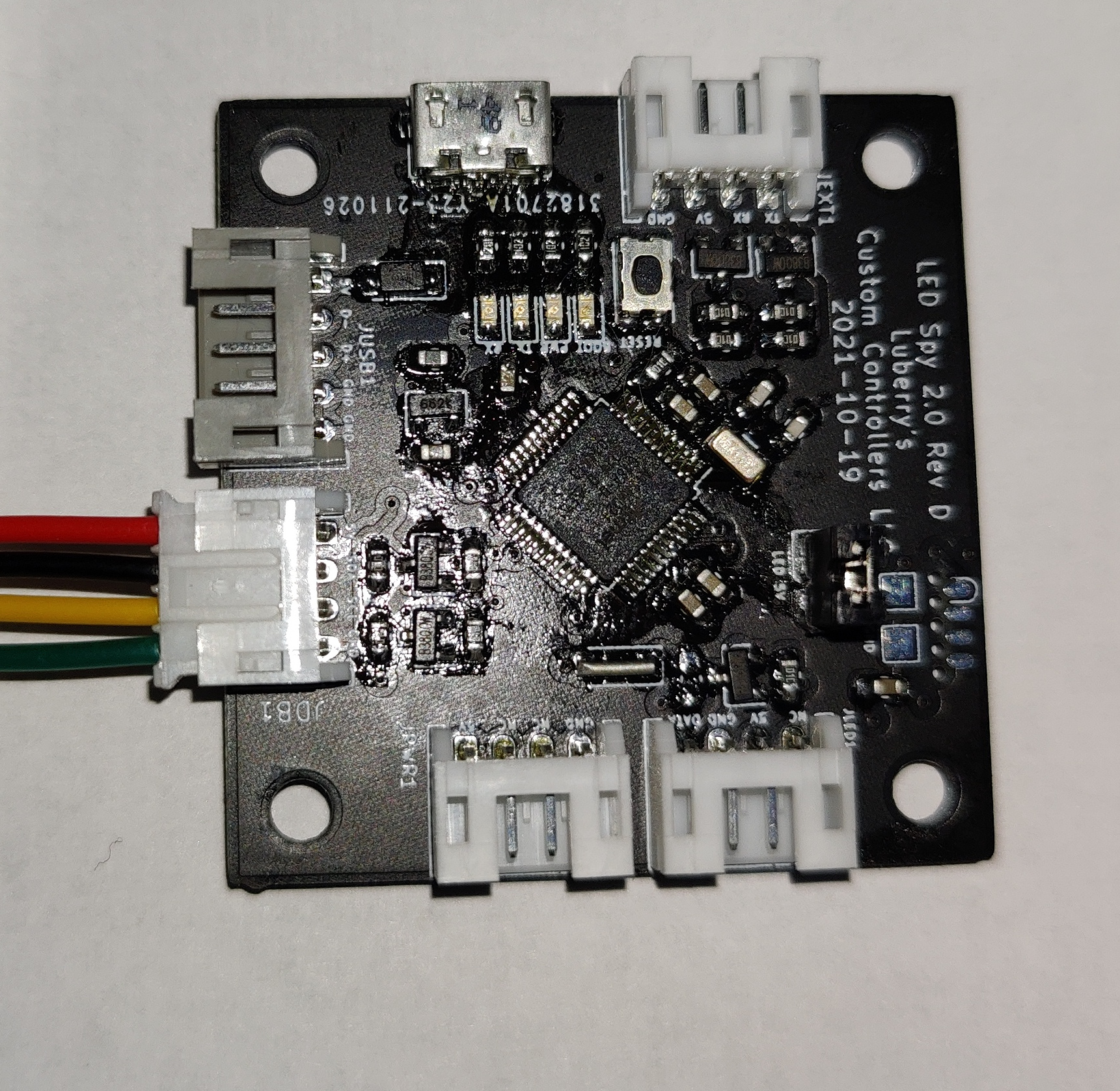
- 1x LCC LED Spy 2.0 Board
- 1x LCC LED Spy Serial Breakout
GEN 1-2 only - 23x LCC 5050 LED Modules or other neopixel/ws2812 led options that supply 2x LEDs per actuator. (optional) 3
- 20x Paradise Kaimana J2 3" Harness (optional) 3
- 2x Paradise Kaimana J2 6" Harness (optional) 3
- 1x Paradise Kaimana J2 8.5" Harness (optional) 9" also works 3
- 1x LCC LED Spy Hub Kit
- 1x LCC LED SPY Battery Bank Wiring Kit (optional) 3
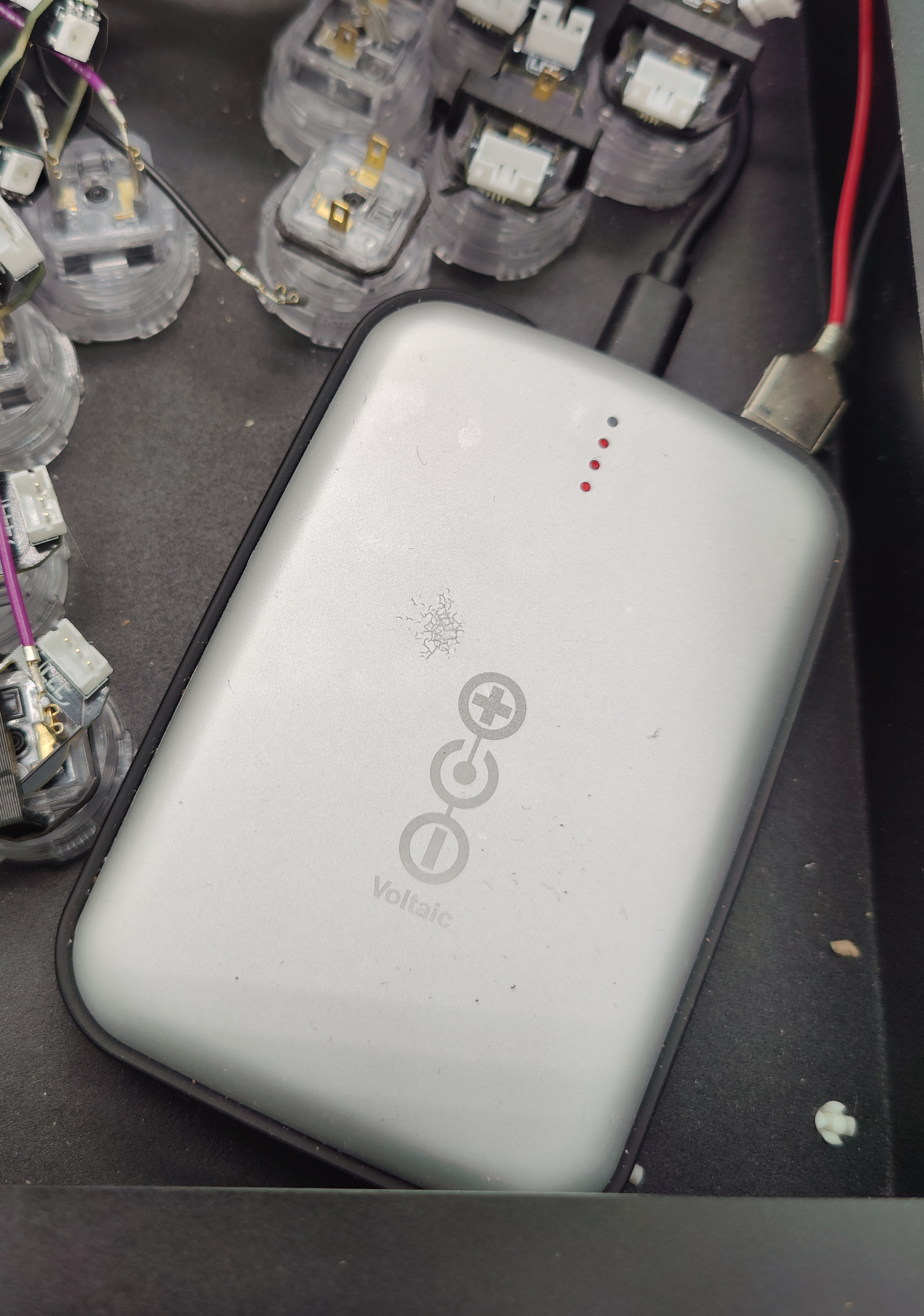
- 1x always on 4 battery bank, my recommendations are below.
- Voltaic Systems V50 (12800mAh)
- Voltaic Systems V25 (6400mAh)
- 1x USB power cable to run your battery bank, if you use the voltaic ones, an A-C will suffice. Just needs to be long enough to reach from the LED Spy Hub to the battery bank.
- 23x 24mm Transparent/Clear buttons 3
- Way to fasten LEDS 3
- Sanwa Buttons - the best way to fasten sanwa buttons is the LCC Sanwa LED Module Mounting Clip
- Seimitsu Buttons - the LCC modules fit snugly around the seimitsu switch so no mounting mechanism is required.
- Crowns/Gamerfingers/Other - a couple small dabs of hot glue are your friend in this instance as i have yet to make a reliable clip design for my modules
- Masking/painters tape used to protect the paint on the surface during cutting 3
- Some way to mark wires (optional, but recommended)
- pen and masking/painters tape work wonders
- Magnet or cup to keep screws together (optional, but recommended)
- 3M VHB (Very High Bond) Tape (for mounting the battery bank) 3
Disassembly
Step 7 you can follow the official guide for disassembly, as it goes much more in depth than this guide.
-
Place your controller onto its face, try and use a soft surface to avoid scratching it.
-
Remove the 6x Phillips Screws (
Gen 3), the 4 phillips and 2 hex screws (more recent GEN 2 Models), or the 4 rubber feet and 2 hex screws (older GEN 2 Models) and remove the base plate. If you are not installing LEDs you can skip to LED Spy Hub Installation.if you have a gen 3 base plate is a good surface to place the controller on top of since it is padded with foam. -
Now is when you should label the wires, this is optional, but will help you later on. You may also take a picture of the wiring. The easiest way to label the wires is use a piece of masking tape around each pair of wires. and write unique labels on each.
-
Now it is time to remove the wires. There are 2 variants of connector used on the Smash Box, Gen 2 and prior used vertical style connector, whereas Gen 3 currently uses right angle connectors. The right angle connectors are significantly easier to remove than the vertical style.
-
Horizontal Removal:
There are 2 main methods for removal of right angle/horizontal quick disconnects.
- Method 1: Use your fingers as demonstrated by the below gif, courtesy of Hit Box Arcade LLC.
- Method 2: Use your needle nose pliers while holding the controller down with your other hand as demonstrated by the below gif, courtesy of Hit Box Arcade LLC.
- Method 1: Use your fingers as demonstrated by the below gif, courtesy of Hit Box Arcade LLC.
-
Vertical Removal:
Since the vertical quick disconects are on super tight, you will want to hold the controller down with one hand, grab the disconnect with the needle nose in the position noted below, and pull straight up.
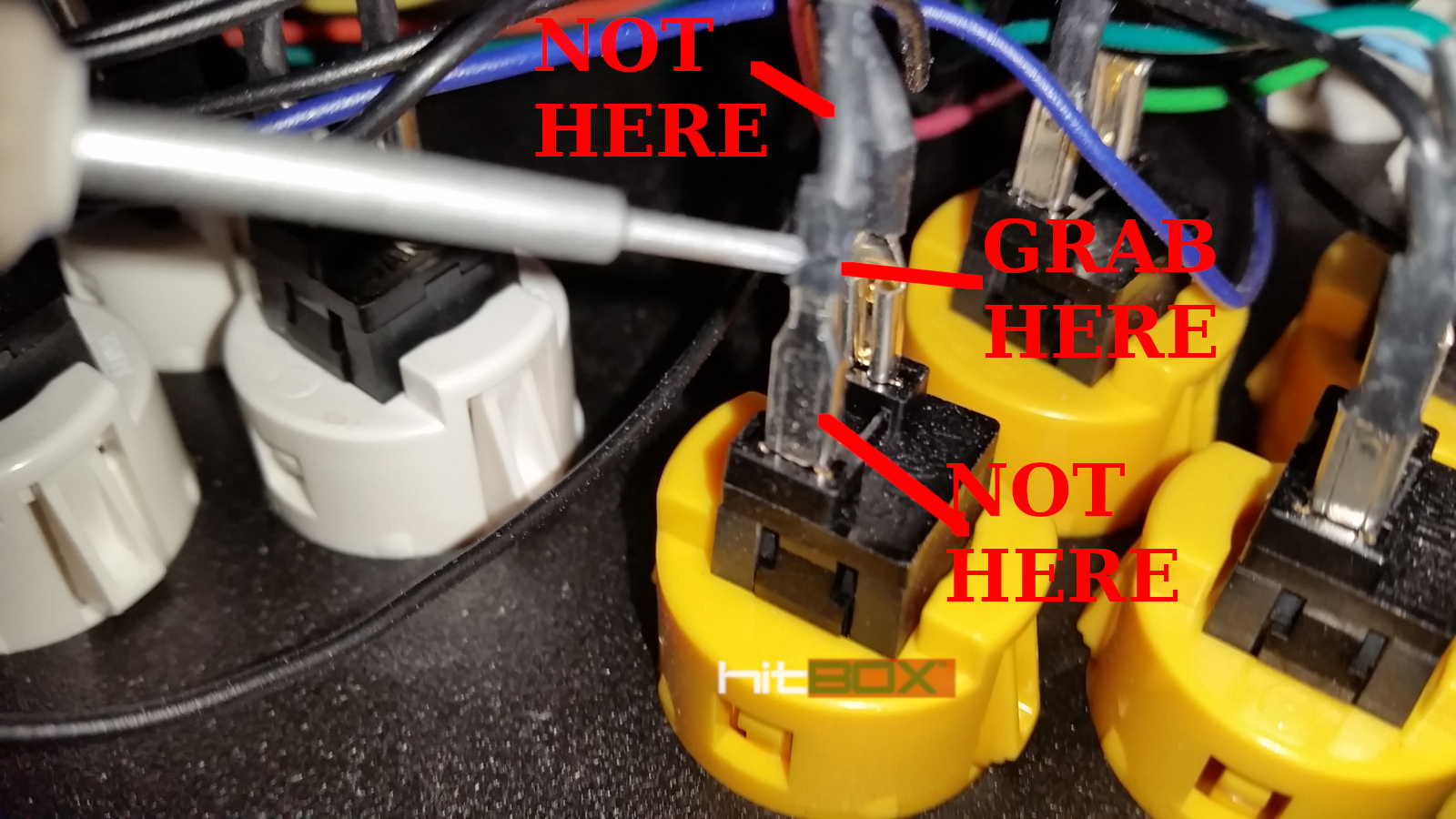
Image courtesy of Hit Box Arcade LLC
-
-
Remove the buttons from the controller, either using the button pop out tool mentioned earlier, or by squeezing the tabs on the buttons with your fingers.
-
Next you need to remove the plastic rivets from the controller, this can be done by pressing on the center pin from the back side with a screwdriver. They should pop out pretty easily this way. Place the rivets somewhere safe as you will need them to reinstall the plexi later.
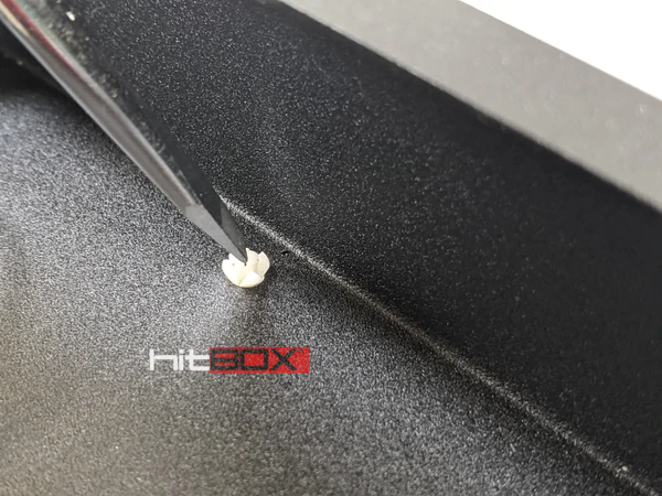
Image courtesy of Hit Box Arcade LLC
-
Remove the plexi and set it aside somewhere it won't be scratched (especially if you plan to reuse it)
-
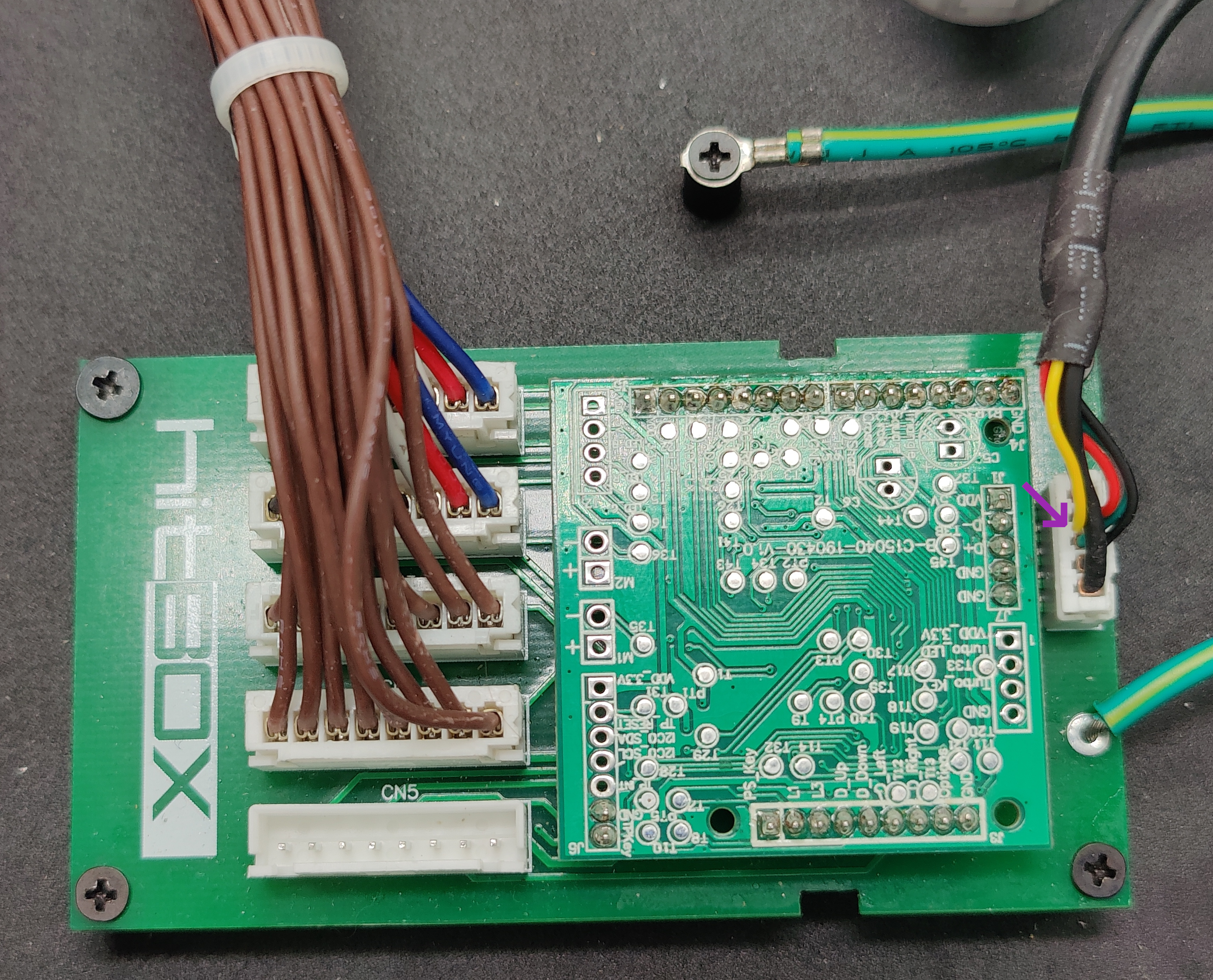
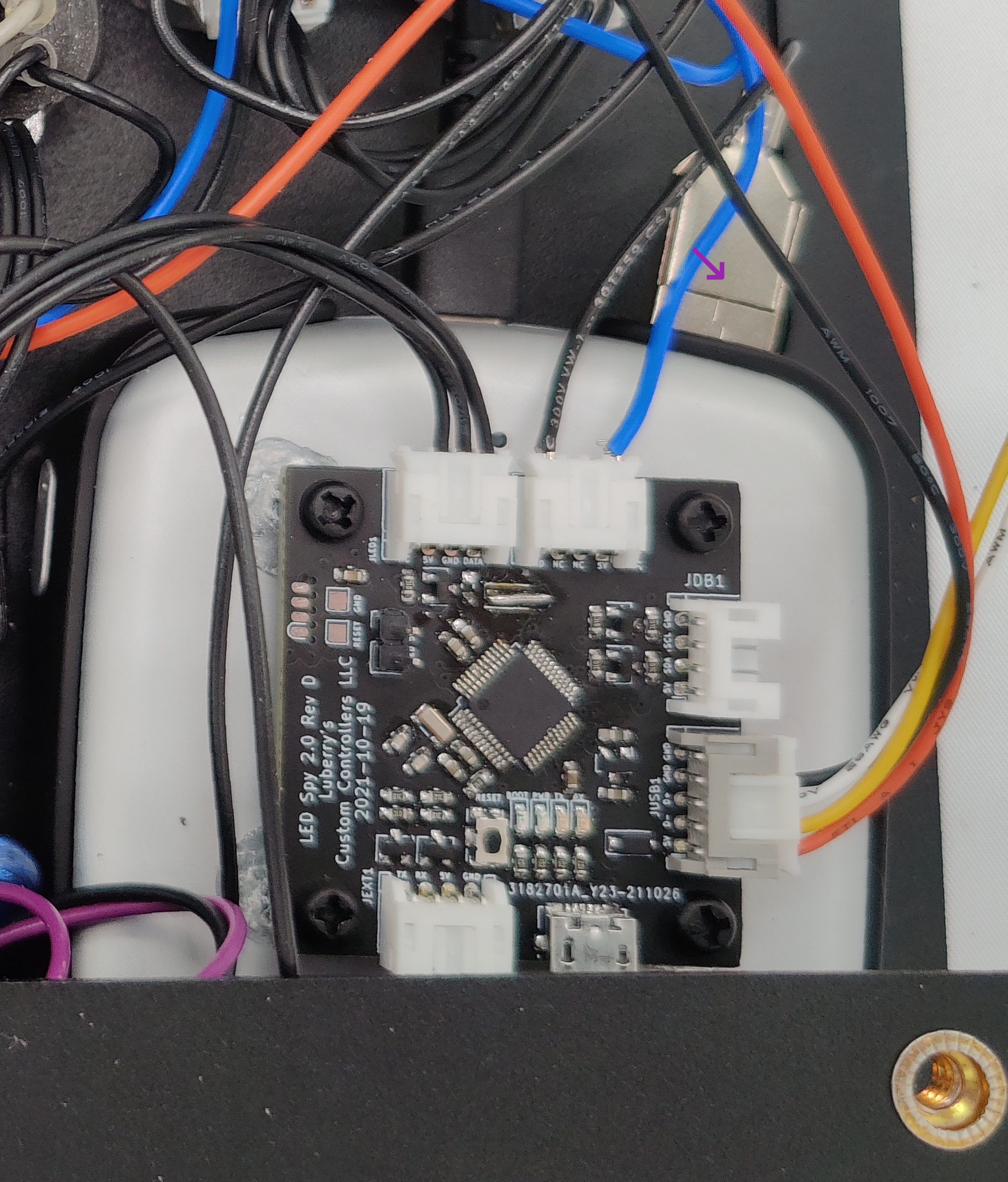
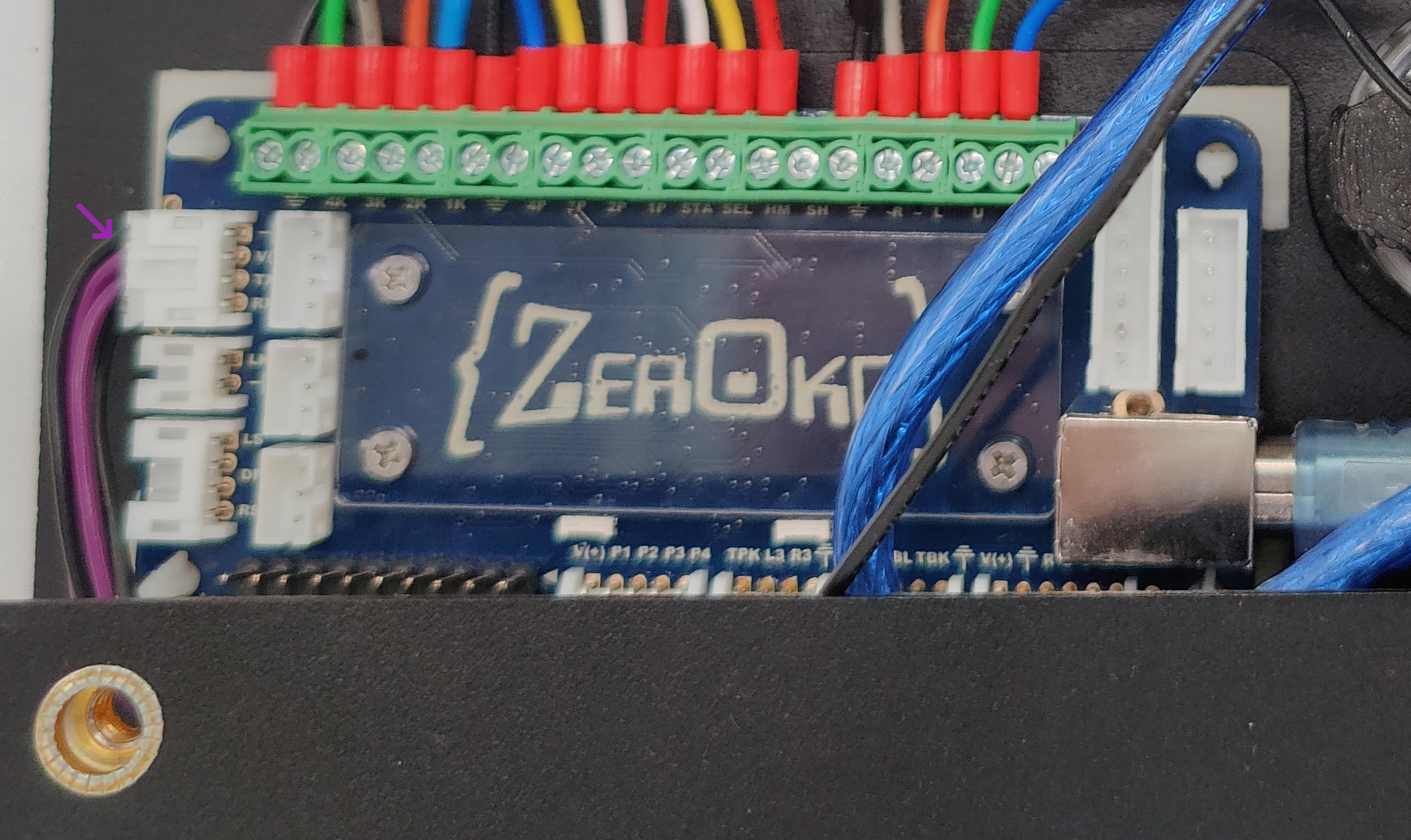
Now remove all connectors for the side ports, and switches.
Take note of the connector locations. You may want to label these with some tapeThe switch connectors can usually be removed by hand, but if not, follow a process similar to theVerticalquick disconnect removal fromstep 4. The connectors to remove are marked below with a purple arrow.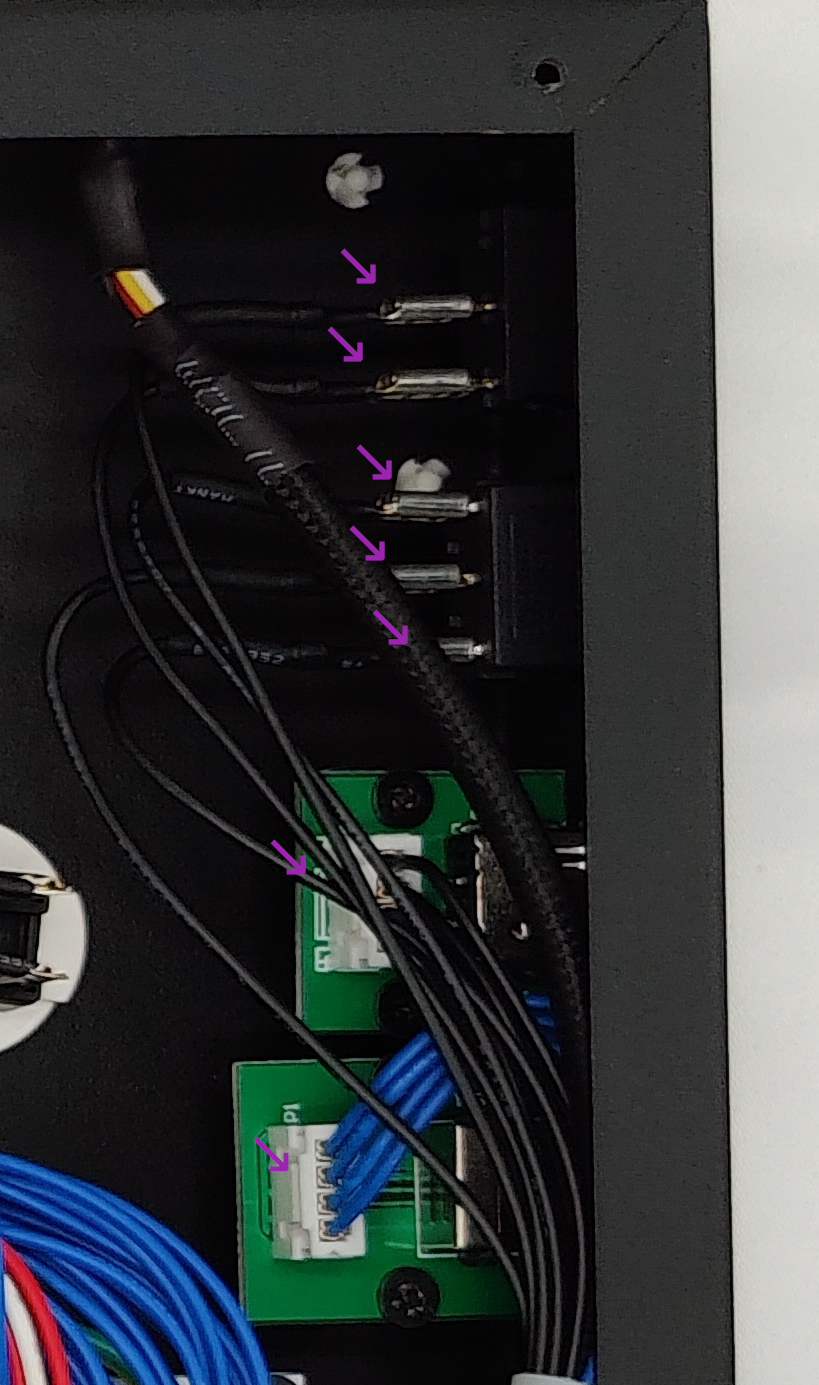
-
Now remove the 4 screws for the side ports denoted below by the purple arrows. If you have a
Gen 2Smash Box, you must also remove the 3 H 2.5 screws on the side as denoted by the white arrows.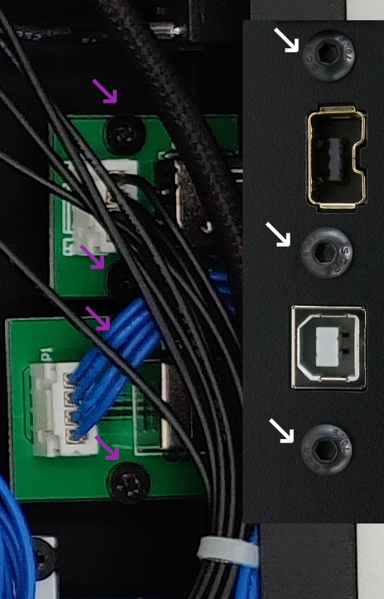
-
You may now remove the side ports and set them aside.
-
Now you must remove the main board. Gen 2 and 3 differ so follow the correct steps for the controller you have.
- GEN 3:
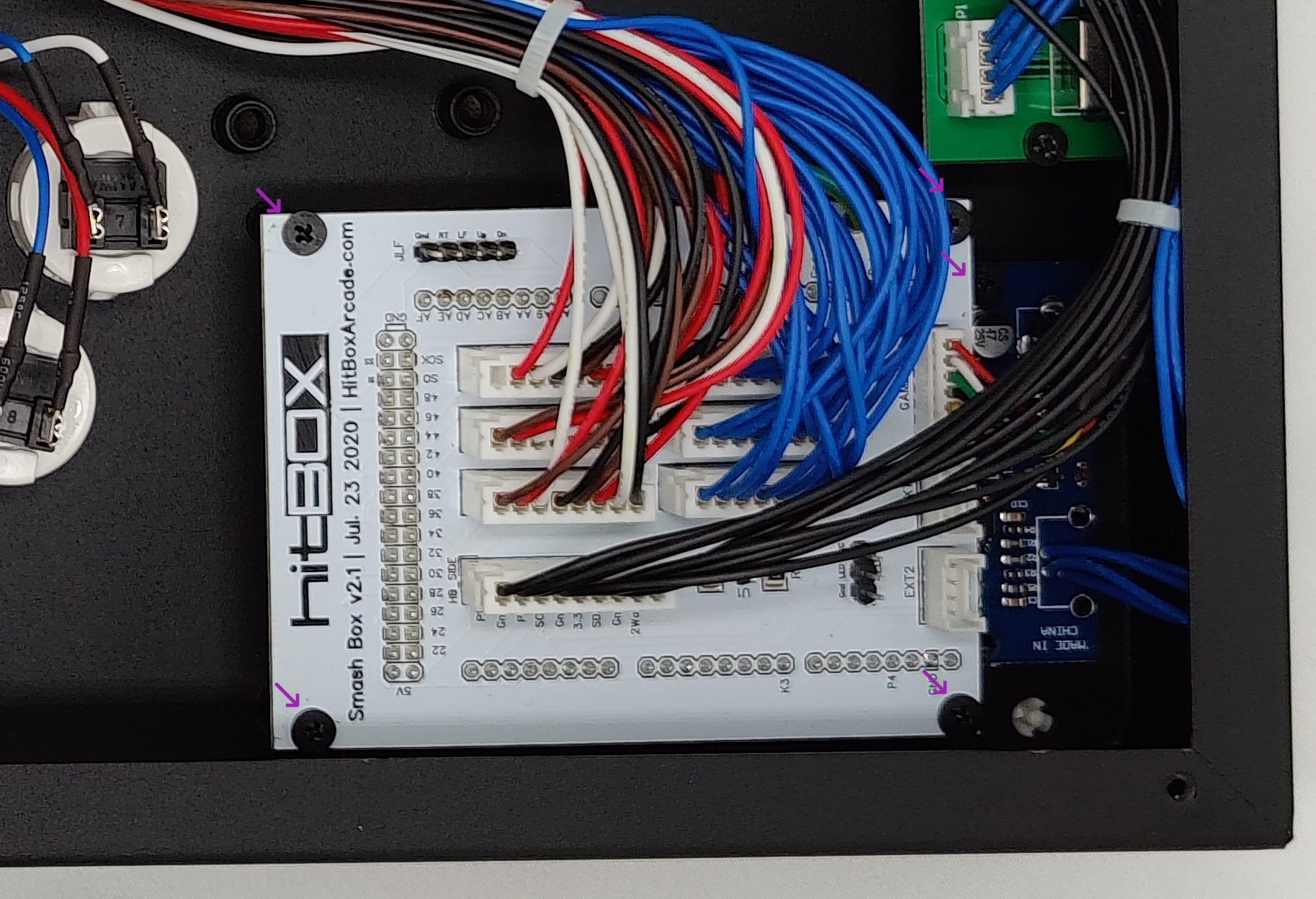
To remove the screws from the gen 3 board remove the 5 screws indicated by the purple arrows in the below image. You should now be able to lift the main board out and set it somewhere safe.
- GEN 2:
The
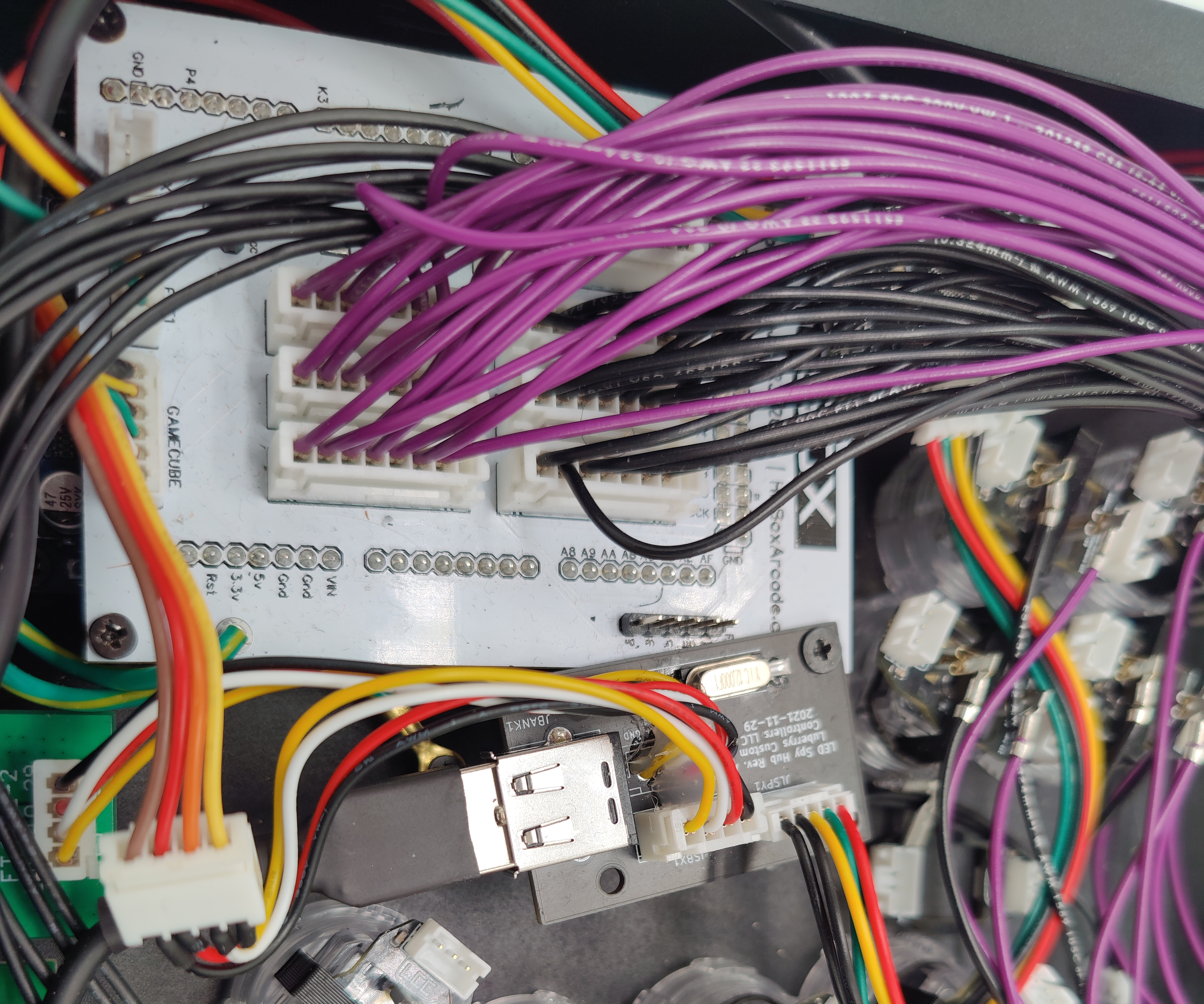
Gen 2Smash Box has screws that are not accessible until you take the top green breakout board off, so it requires multiple steps.- Remove the 4 main pcb screws pictured below (there is one under that bunch of cables, trust me)
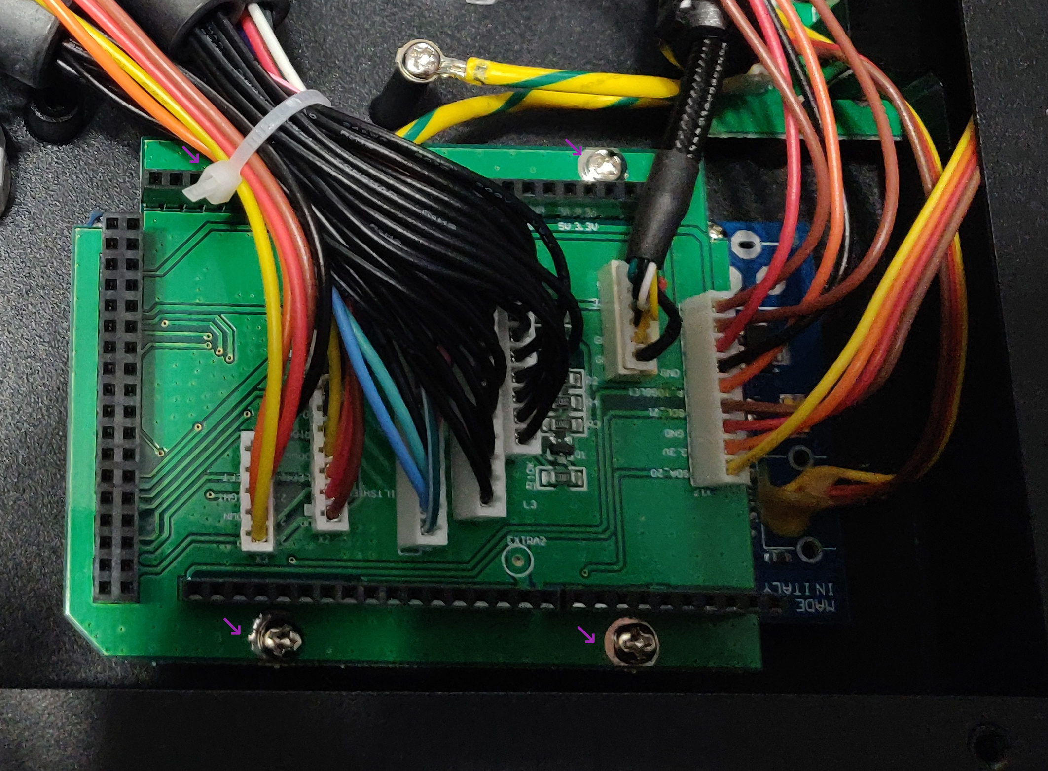
- Gently lift the green pcb off of the blue one underneath. It may be a bit tight, but try to apply even pressure to remove it.
- With the board off, there should be 4 more screws holding in the blue pcb. Remove those, and lift it out.
- Remove the 4 main pcb screws pictured below (there is one under that bunch of cables, trust me)
Power Switch Installation
Now it is time to prepare to cut the hole for the LED power switch.
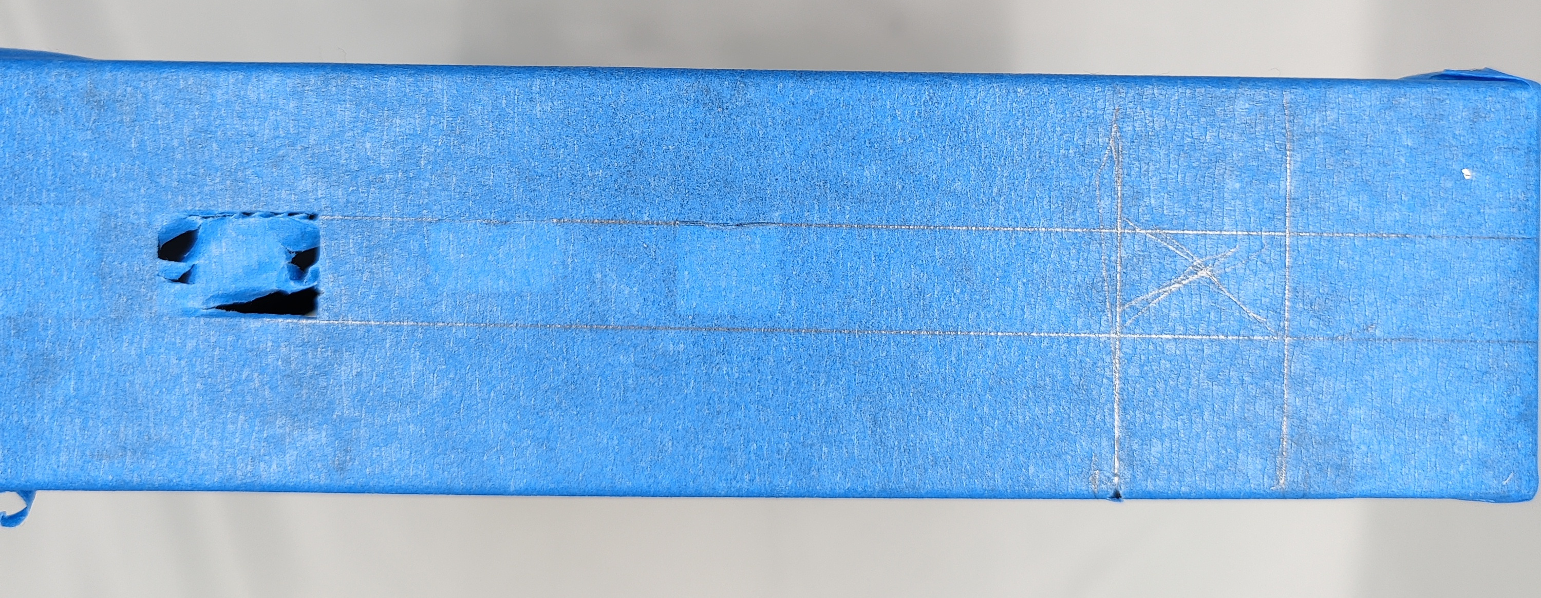
- First, to prevent scratching the case you should wrap the edges in some sort of masking/painters tape, this will also let us easily mark our hole for our switch as shown below. This guide will assume you are using the switch supplied with the wiring kit we sell, as it is a close match to the switches already installed. You want to mark out the rough location to give you a guide when cutting the hole, and try and line it up with the existing switches.
- Now, take your center punch and mark a spot in the center of where you plan to install your switch.
- Drill a hole where the center punch mark was made that is slightly smaller than the switch (give your self some room to adjust)
- Now, with the hole drilled, use either your files to make the hole rectangular, or rough it out with the dremel and burrs.
- Gradually fit the hole to the switch, making sure to check the fit. You want the switch to fit snugly.
Battery Bank Installation
Now to install the battery. This is easier prior to full reassembly, as plugging in the cables can be difficult with the main pcb installed.
- First you will need to use some VHB tape to secure the battery similar to the figure below. you can use more than pictured to secure it better.
Make sure to clean both the battery and inside of the case with some sort of degreaser, or isopropyl alcohol to promote better adhesion
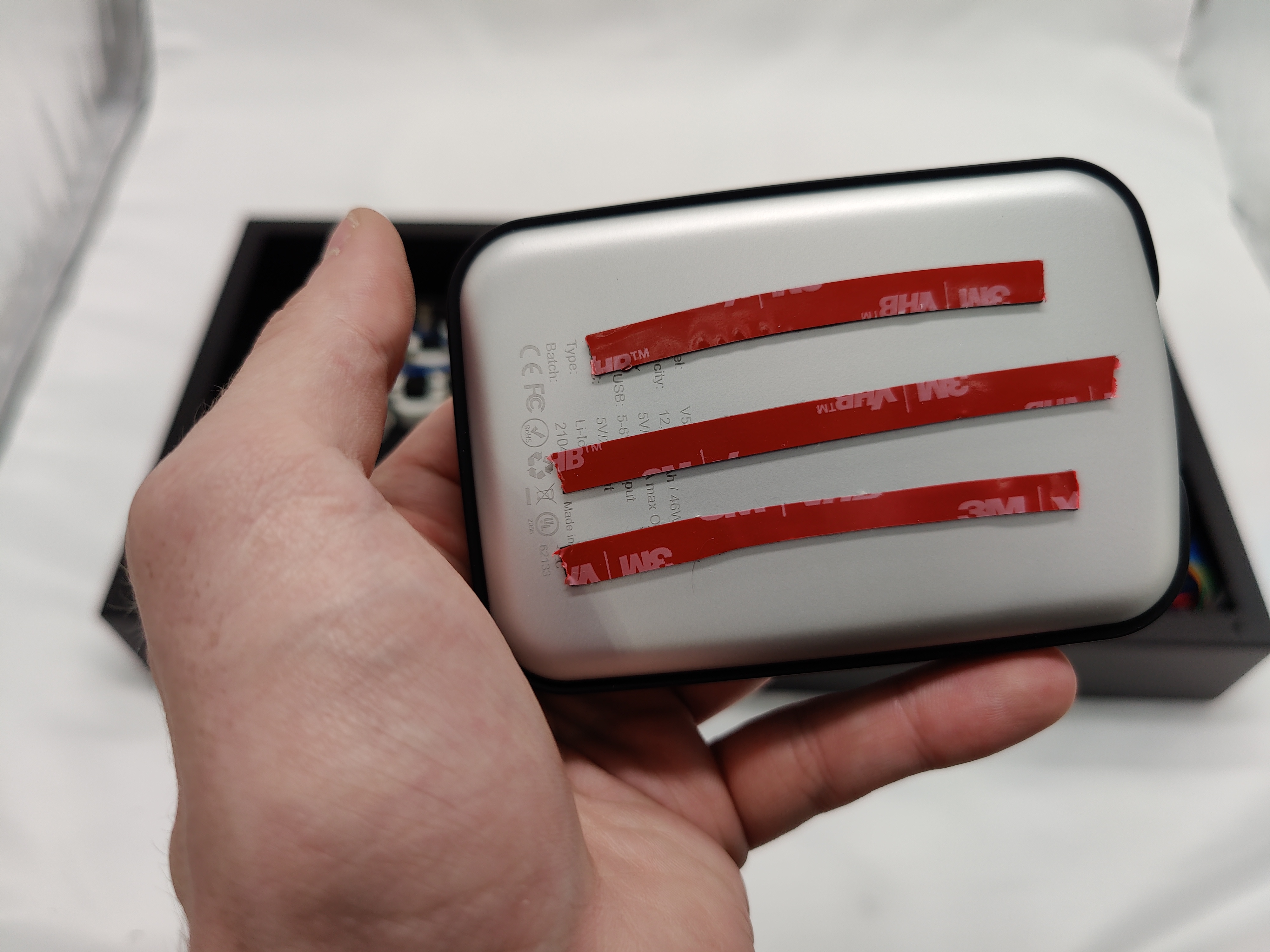
- Peel the backing from the tape on the battery and stick it down in the position shown. Make sure you will still have access to the charge port and one output port for wiring.
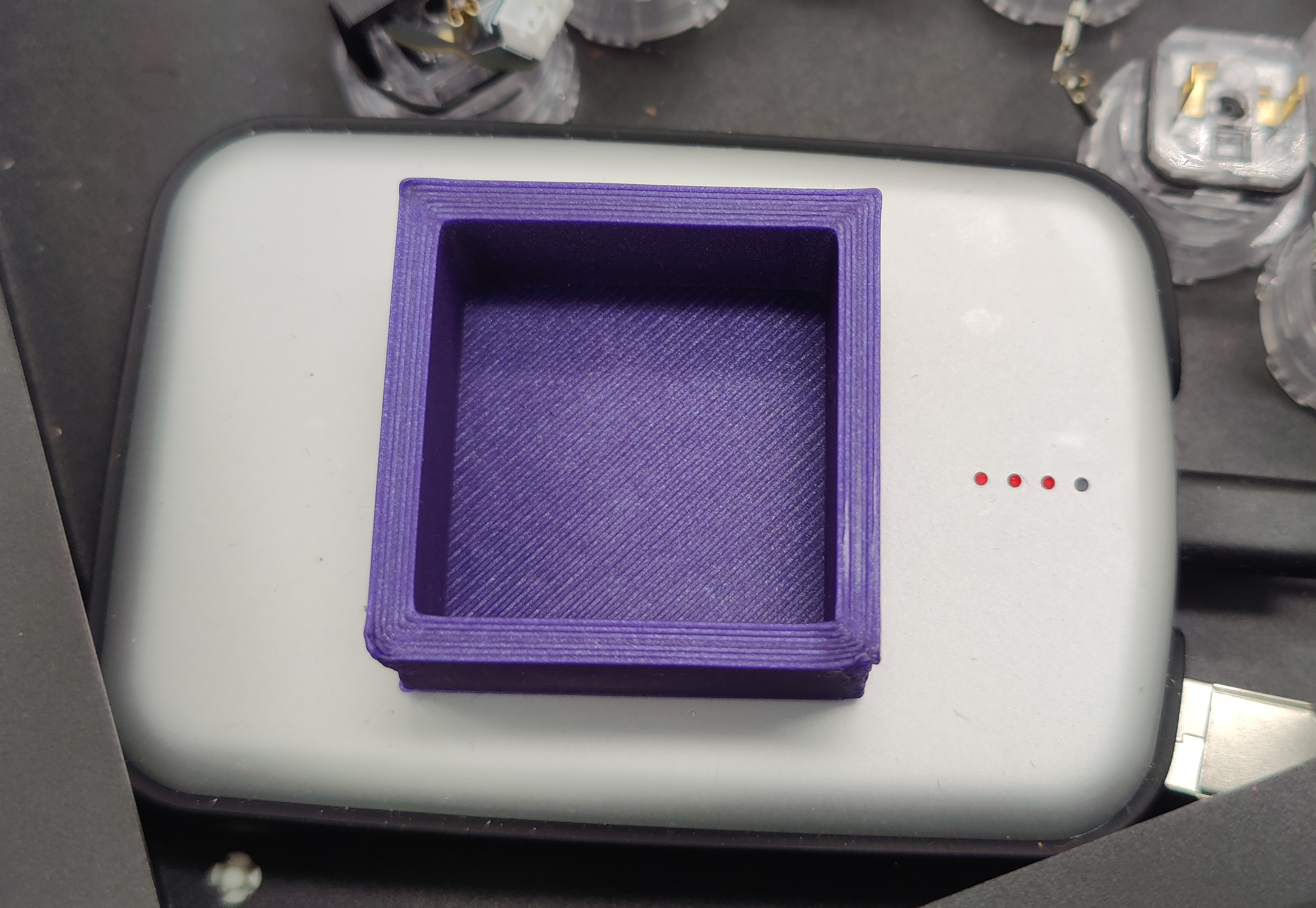
- Now install the battery hold down block that came with the battery installation kit. first remove the red film from the back side of the block.
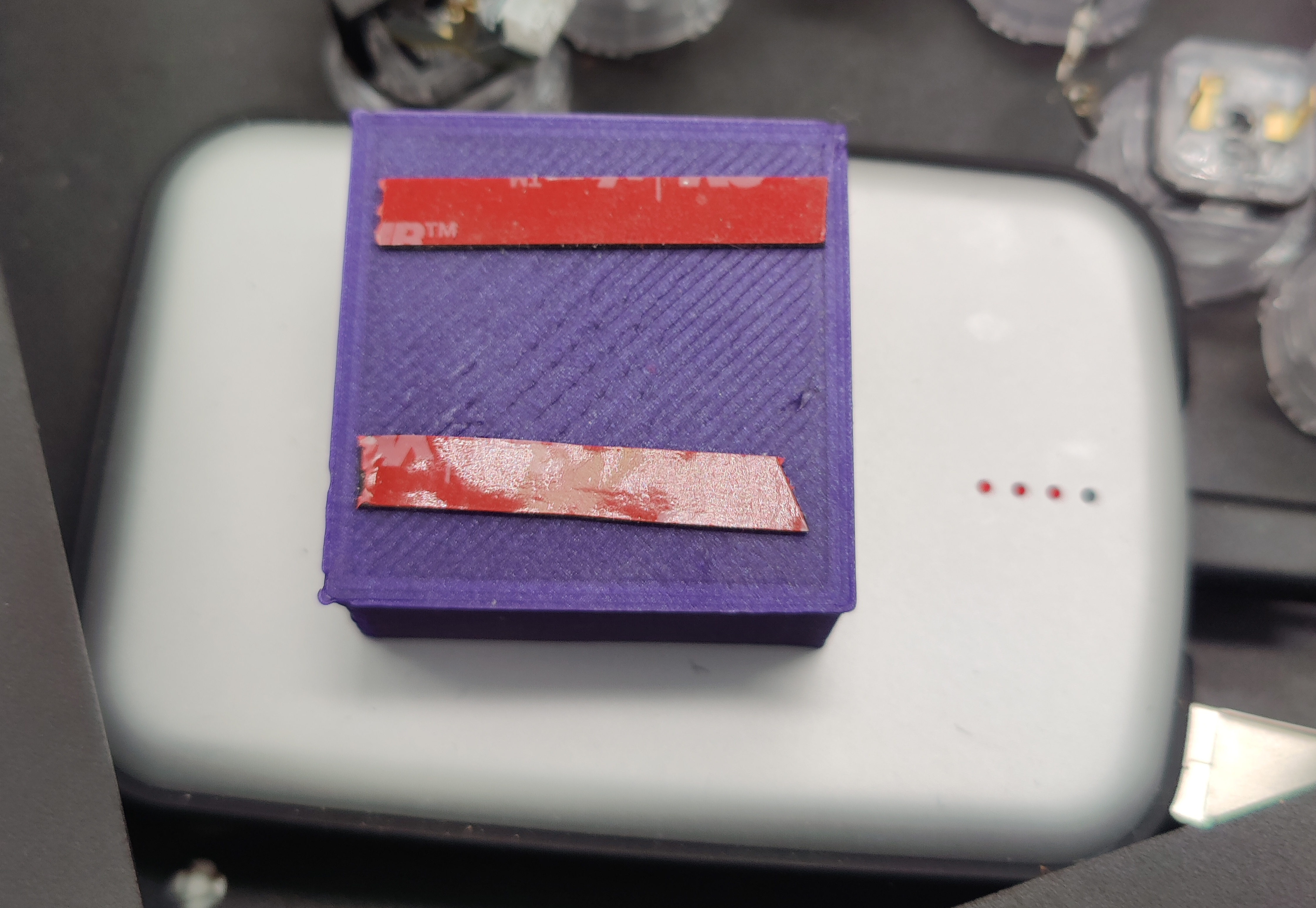
- Next stick the hold down block to the battery. This will help prevent the battery from falling down over time by pressing against the bottom plate.
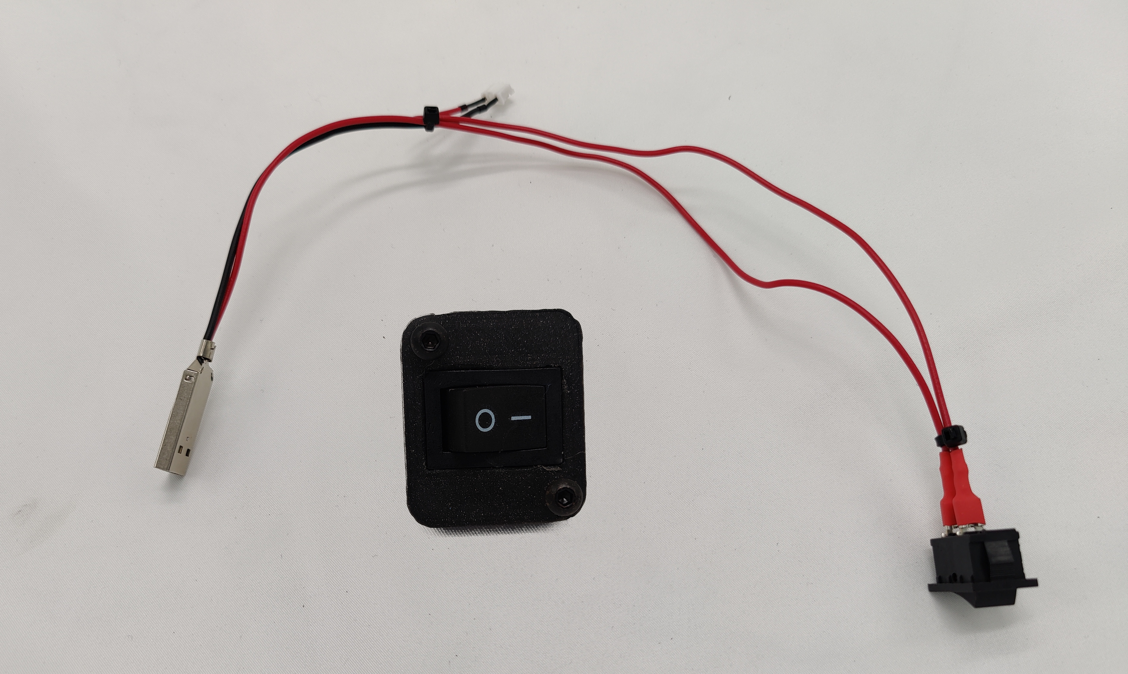
- Next wire the battery harness to the power switch. If you purchased the wiring kit you should have received a cable similar to the one below.
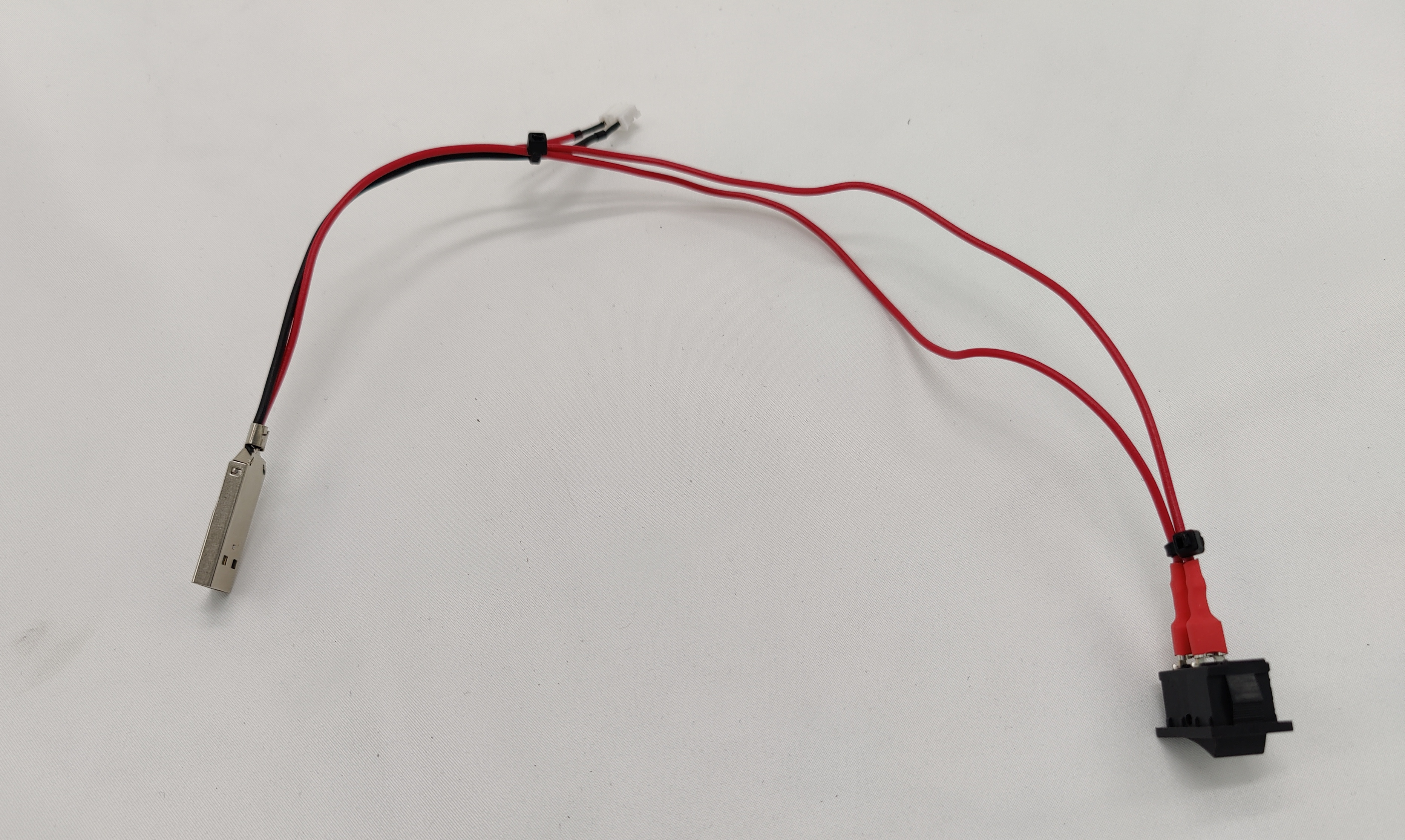 When wired to the switch, you may need to bend the leads a bit to clear the controller main board as shown below.
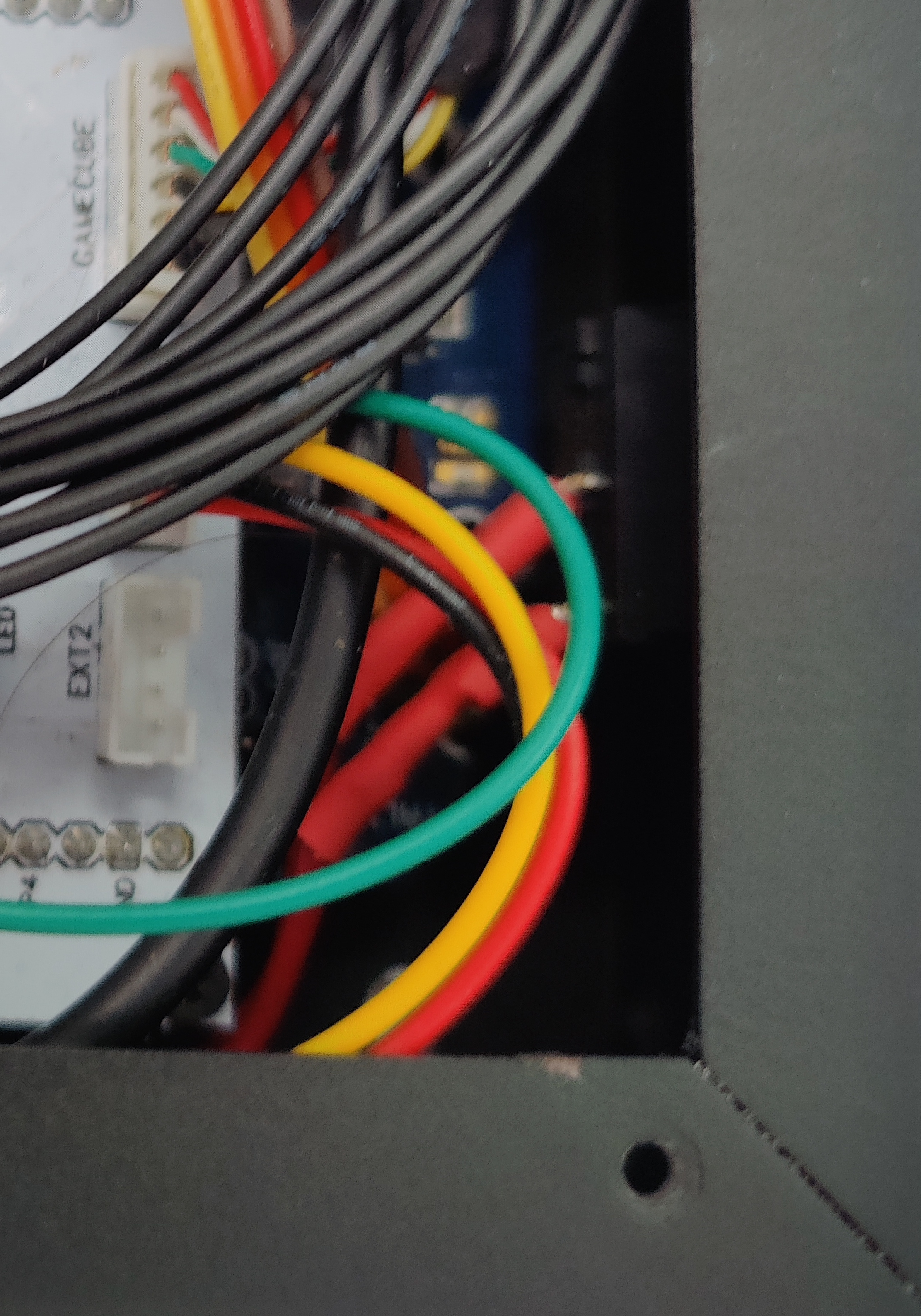
- Now we plug the USB-A end of the harness into the usb port closest to the outside of the case as shown.

- Assuming you have the voltaic battery. Plug in the charge cable type c port into the battery bank. we will route this later.
Reassembly (Part 1)
Now it is time to begin partially reassembling your controller, you can either follow my below steps, or the official guide through step 6B.
- First, reinstall your plexi, and the rivets. And press them in until it clicks, as pictured below.
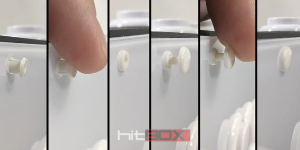
Image courtesy of Hit Box Arcade LLC
- Now insert your buttons, you may need to adjust their positioning later to fit the leds. Make sure they fully snap into place.
- Reinstall the side ports and screws. (the reverse of Disassembly
step 9) - Reinstall the main board. (the reverse of Disassembly
step 10) - Reinstall all side port cables except for the usb port one, we will come back to that later. (the reverse of Disassembly
step 8)
LED Installation
The next step is to install the LED Modules, this guide will assume you are using the LCC 5050 LED Modules.
- First position all of your modules so that they don't interfere with eachother. you may have to rotate the buttons some to get them all to fit. (its a bit of a puzzle).
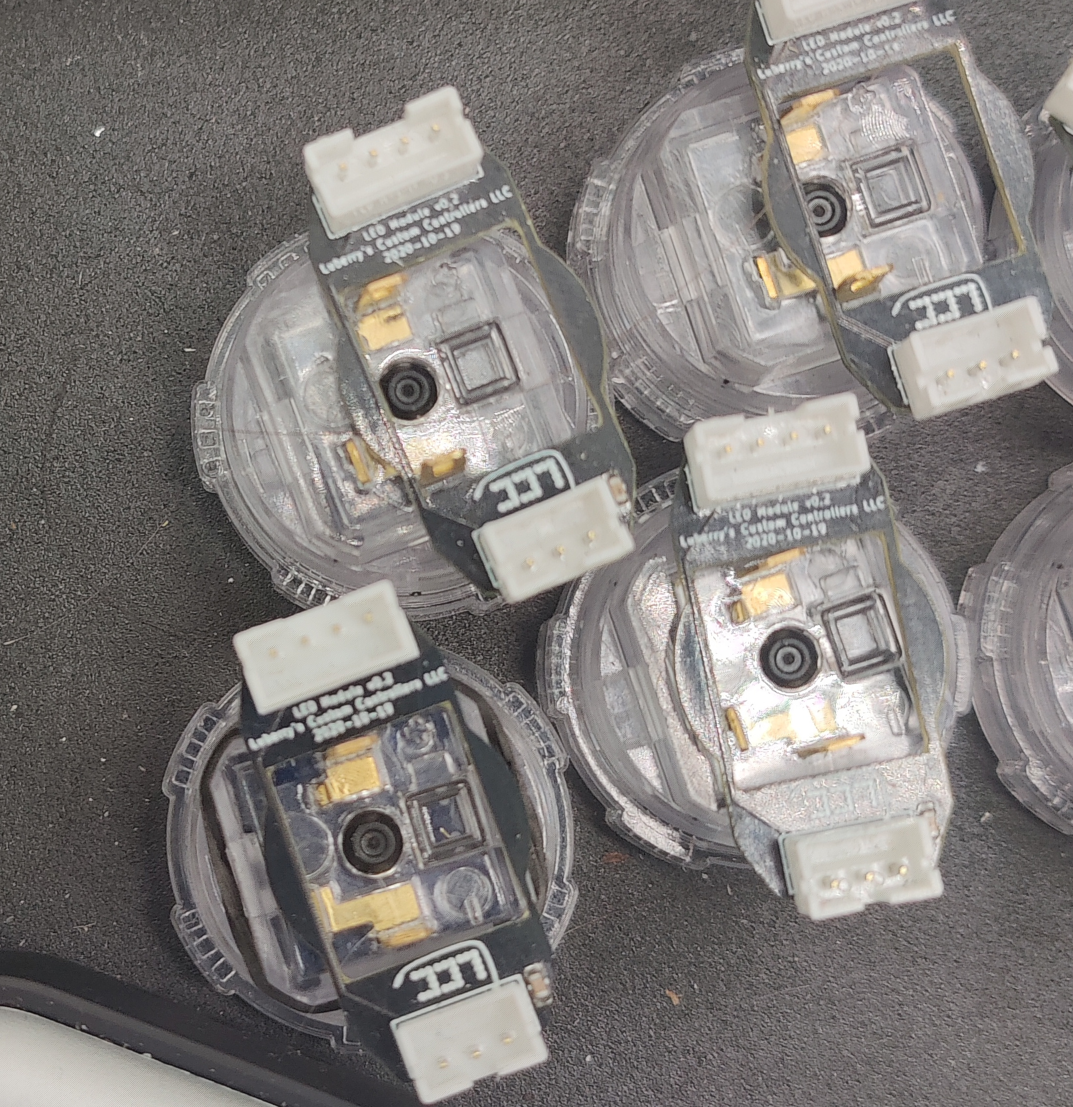
- Now either secure the modules with some hot glue, or my LED clips (for sanwas) making sure the wires quick disconnects will still plug in.
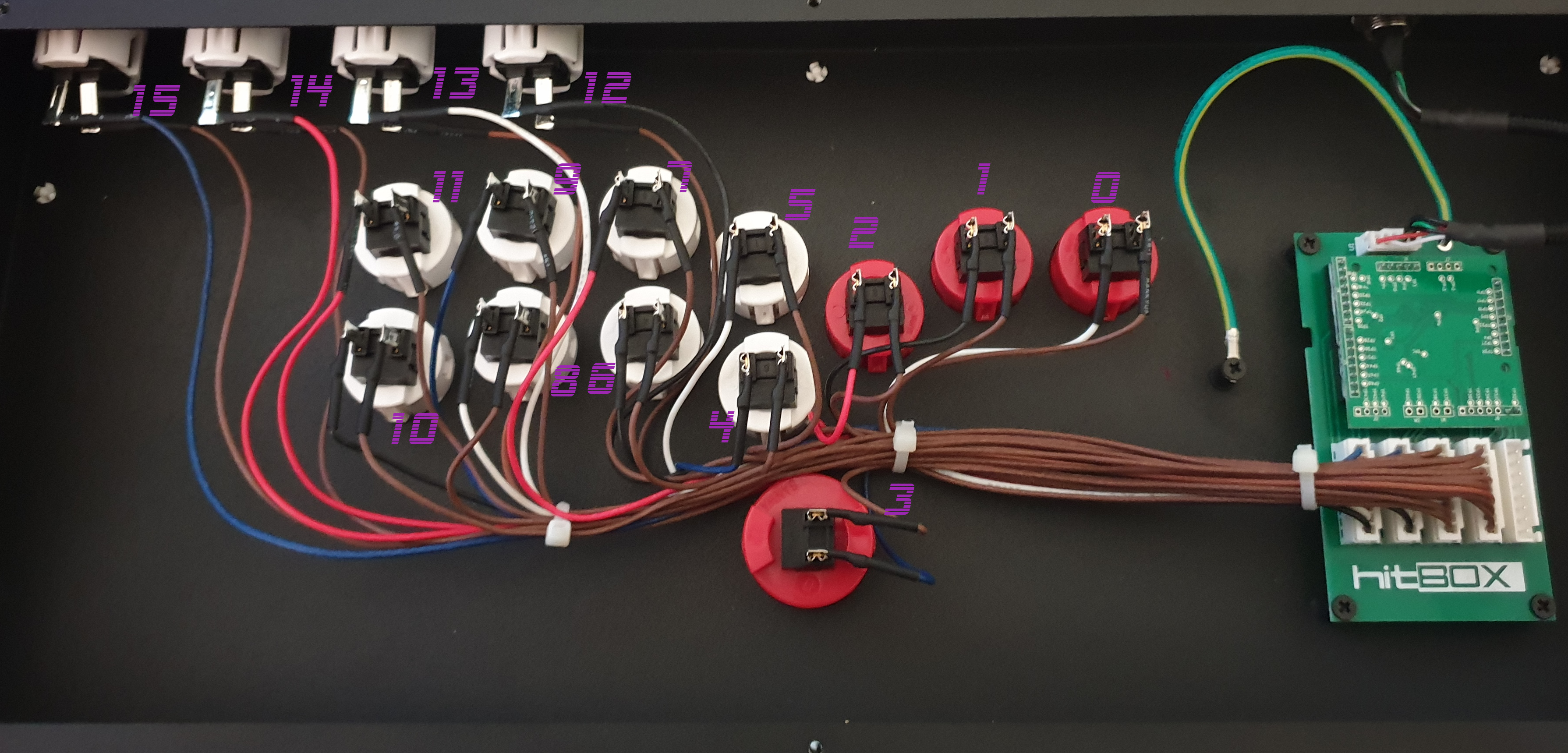
- Next we need to connect the leds. There are two different connectors on the leds. The 3 pin is the input, and the 4 pin is the output. Route your cables as you see fit as you can always remap the positon in software, however you want the input to be pretty close to the main pcb. Below is probably the optimal routing.
All connections except for the following use the
3"cables:Connection Length LED Spy -> 0 6" 10 -> 11 6" 21 -> 22 8.5" or 9" 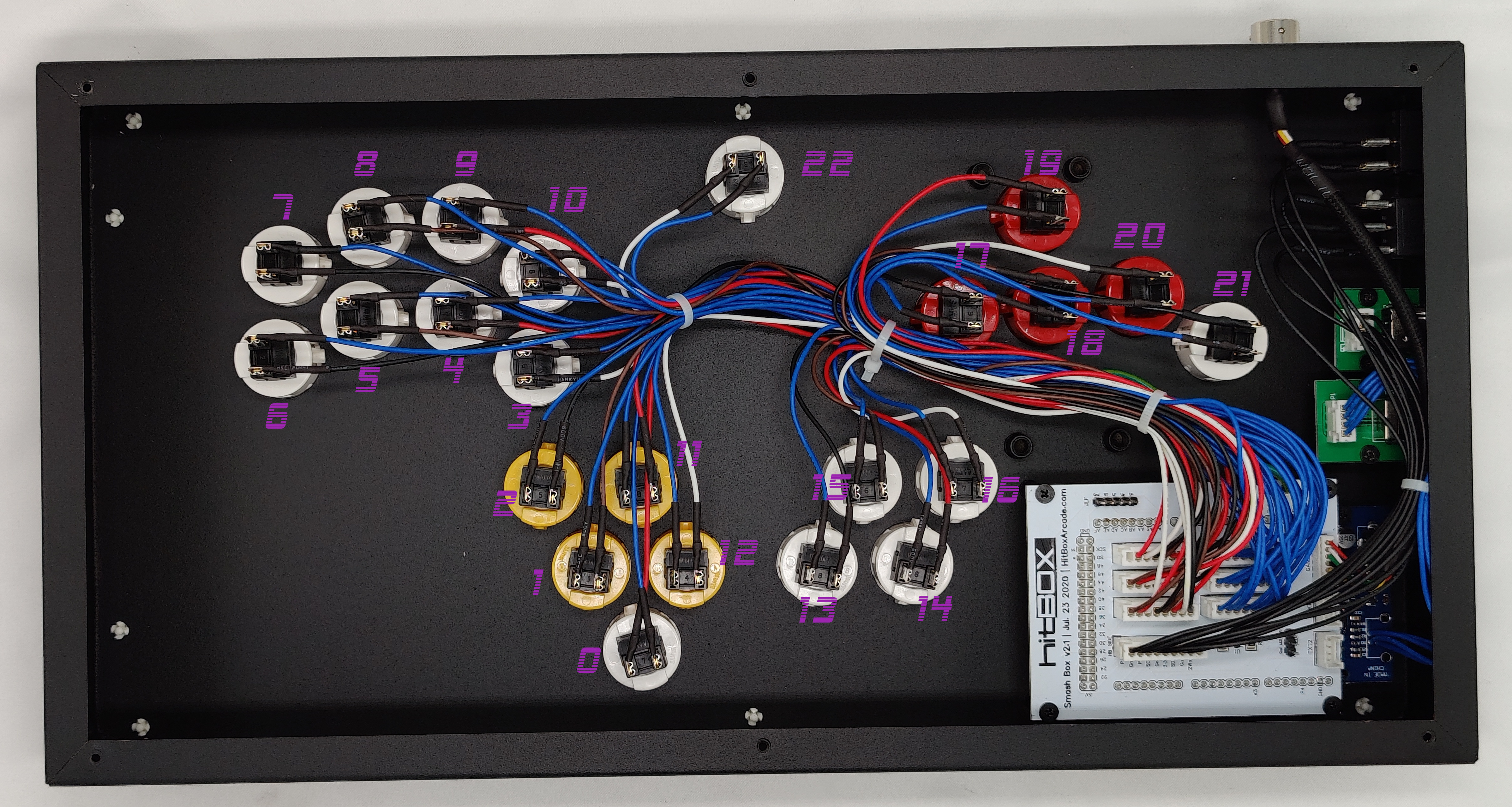
- Once the leds are wired, reconnect all of the quick disconnects to the correct buttons.
LED Spy Hub Installation
Now it is time to install the LED Spy Hub which lets us reuse the side usb port for both battery bank charging, as well as for led spy and Smash Box programming.
- First we need to install the LED spy Hub. For both
Gen 2andGen 3we should be able to mount the hub in roughly the same spot. To begin we want to remove the screw marked in the image below. On the left is theGen 2and right isGen 3.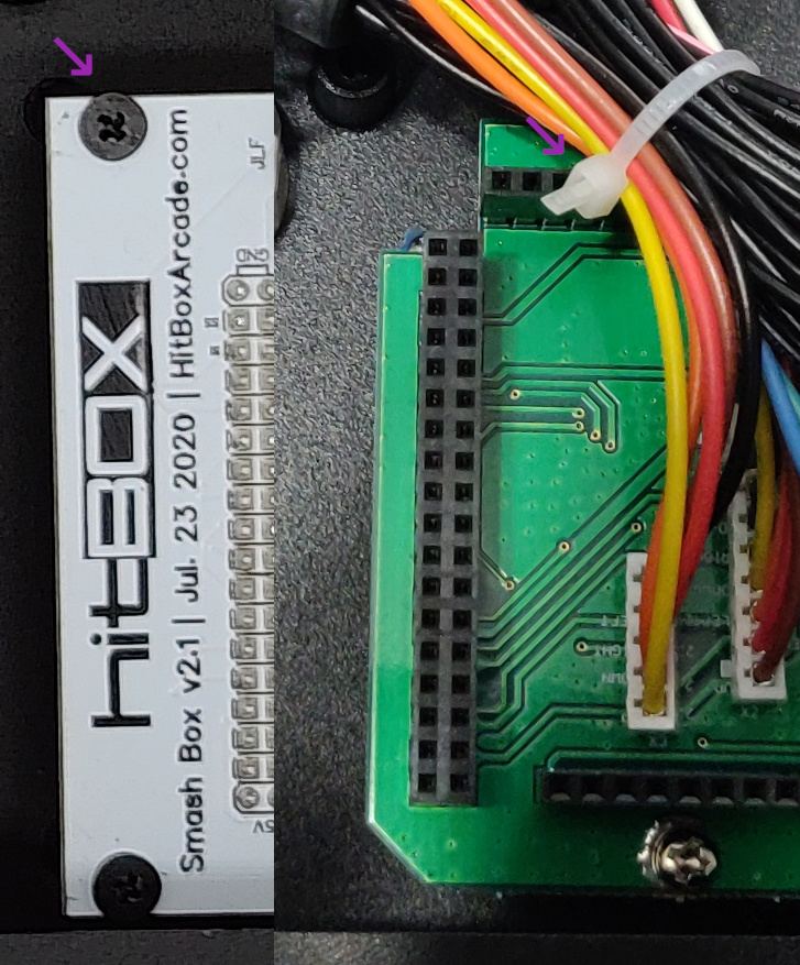
- Now mount the hub as shown below.
- Now, take the plug meant to go into the usb side port and plug it into the matching 4 pin header on the hub labeled
JSBX1 - Take the hub's included 5 pin JST cable and plug one end into the hub, leave the other end be, we will come back to this later.
- Take the 4 pin cable attached to the hub and plug it into the side port USB.
- If you are running LEDS, Take the USB A end of your battery bank charge cable you installed earlier and plug it into the USB A port on the hub.
LED Spy Board Installation
Now the LED Spy Board can be installed.
-
First plug the included 4 pin JST cable into the port labelled JEXT1 on the LED Spy PCB as pictured below.
-
Next you must mount the PCB. Here we have another instance of
Gen 2andGen 3differing.Gen 2: ForGen 2you will need to mount it to the body of the controller with 3mm adhesive standoffs which you can pick up from our friends over at Bit Bang Gaming here. Below is the rough positioning as I don't have an availableGen 2Smash Box for mockup.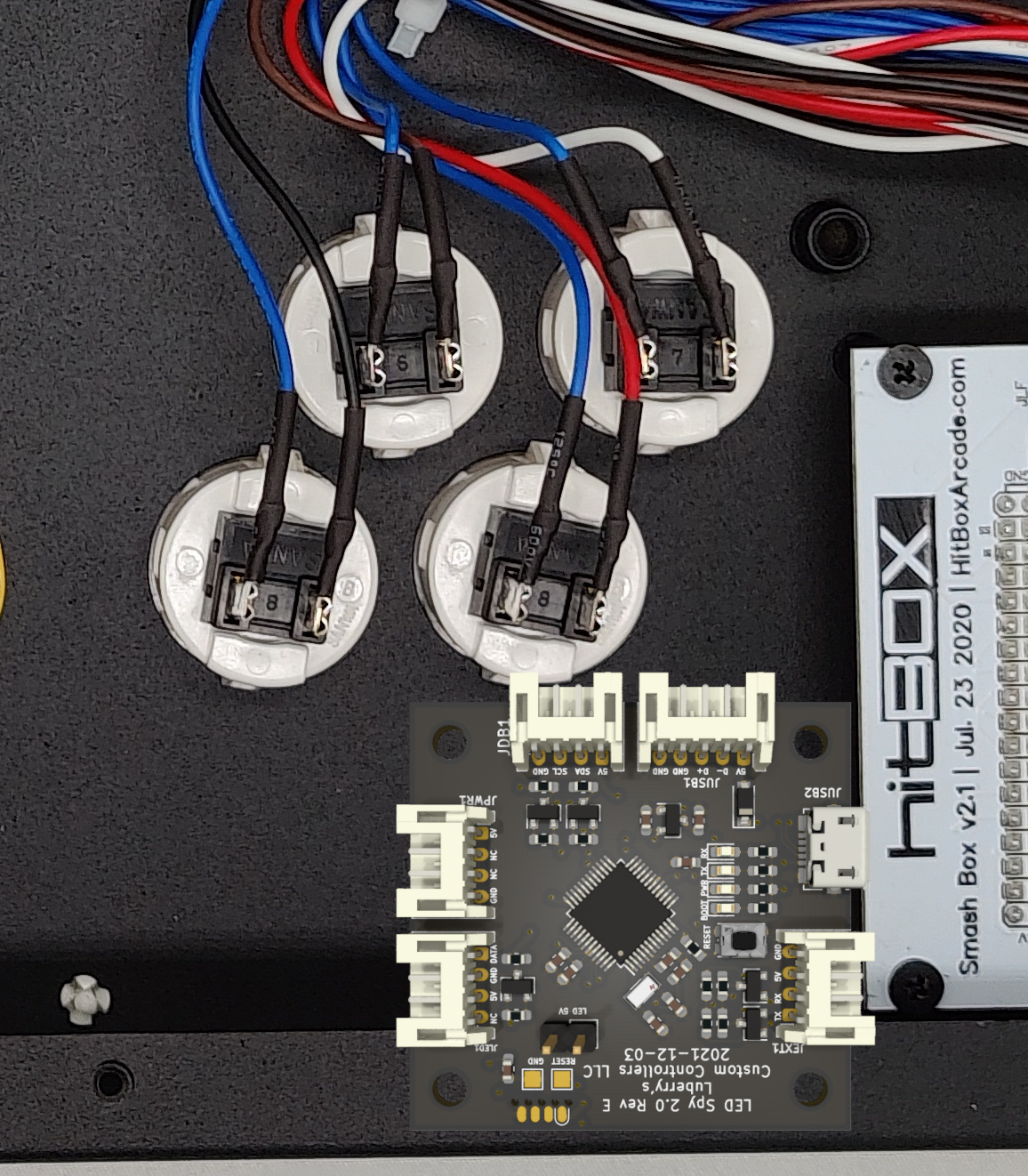
Gen 3: ForGen 3you can either mount it like you did above for gen 2, or you can make use of the bottom left screw hole on theGen 3PCB as shown. Make sure to place a plastic washer between the two boards and mount it as as shown below.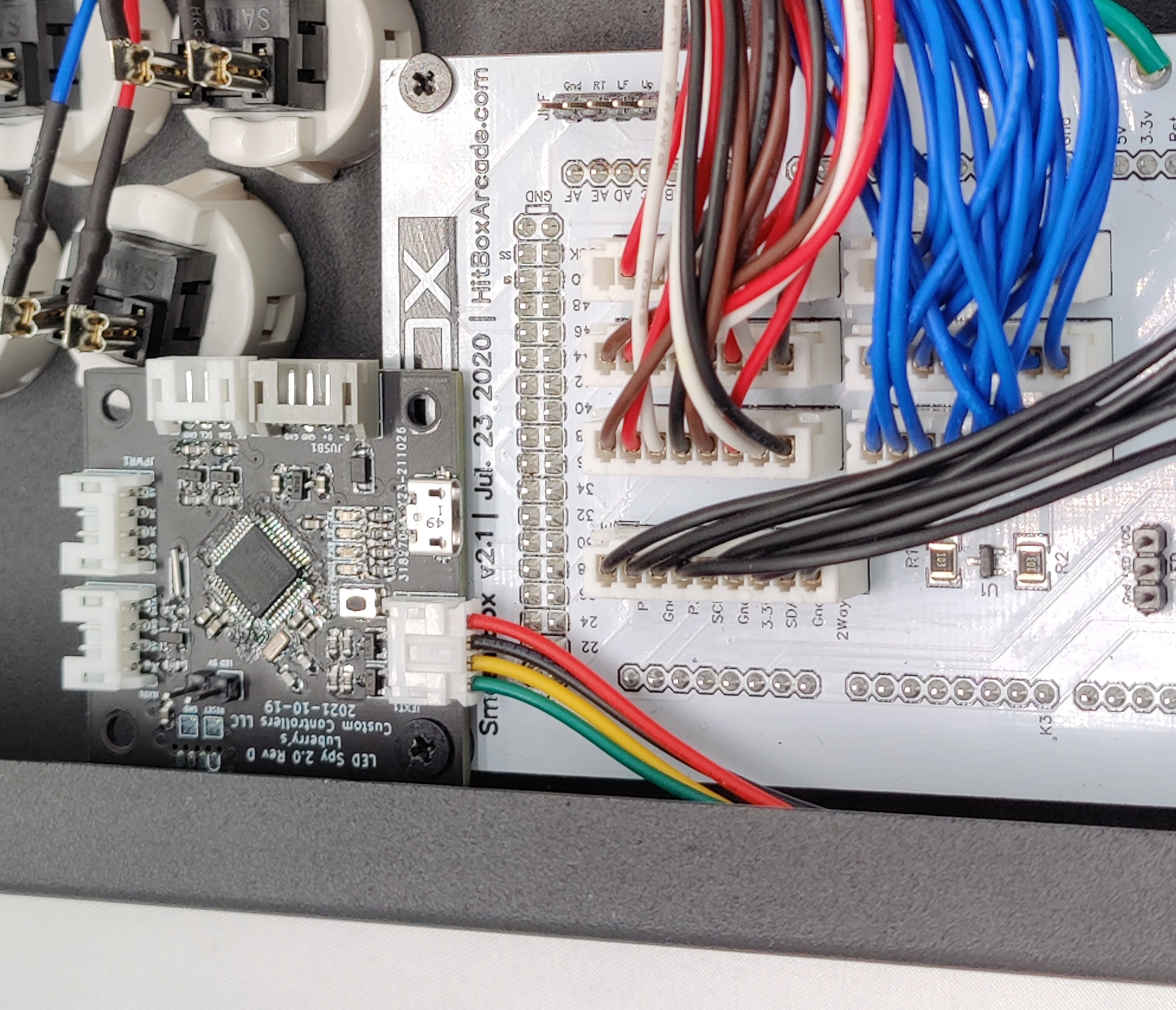
-
Now we can plug LED Spy board into the Smash Box PCB, again this step is slightly different between
Gen 2andGen 3-
Gen 2: There are a couple of steps for this variant listed below.- First we must install the
LED Spy Serial Breakoutas pictured below.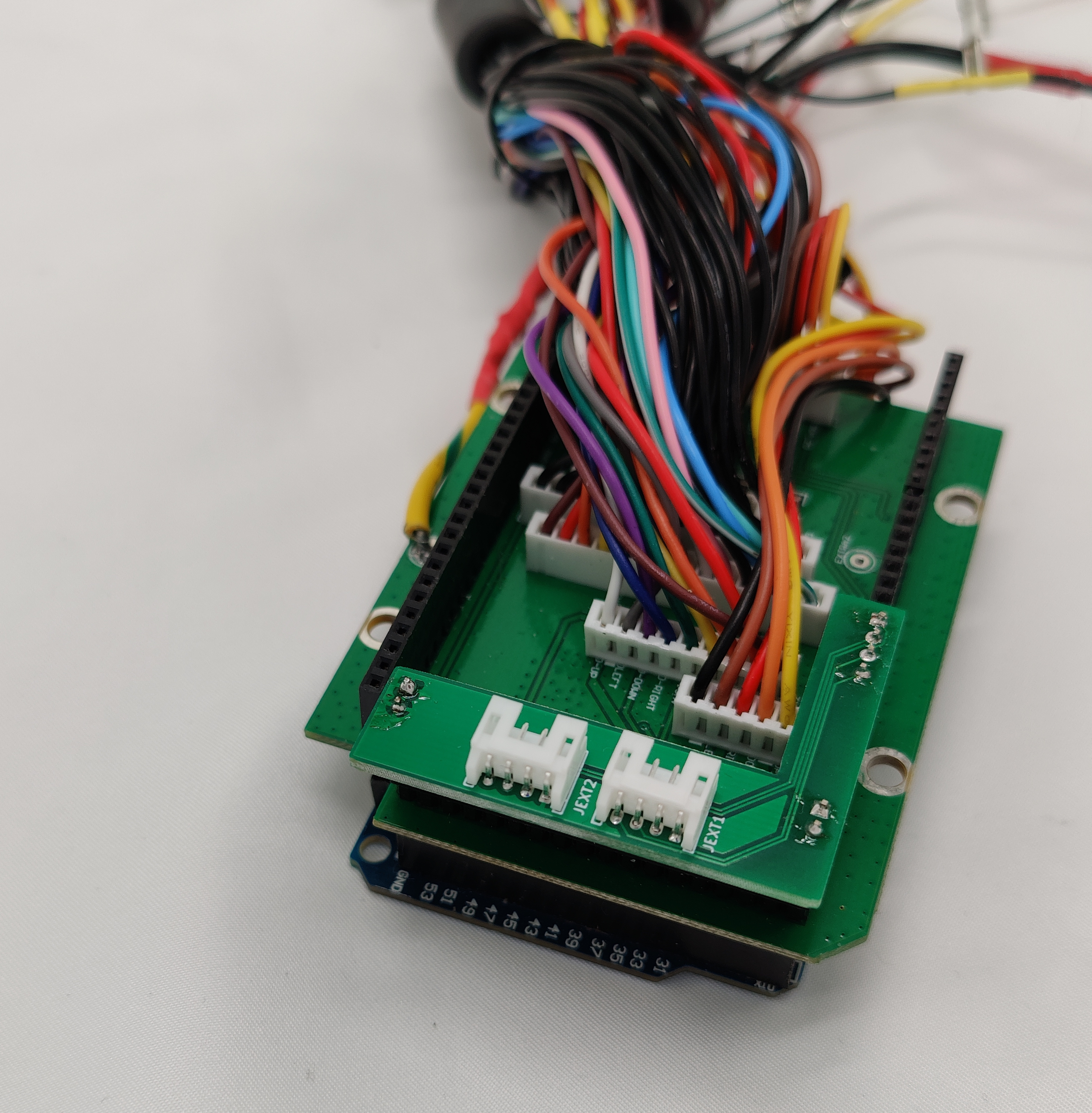
- Now plug the free hanging end of the 4 pin JST we plugged into the
LED Spyboard earlier into theJEXT1port of the breakout
- First we must install the
-
Gen 3: Gen 3 should just be mostly plug and play. You should just need to plug the other 4 pin connector from the board connector into theJEXT1portThere is a minor connector difference on some gen 3 boards, and you may need to trim the connector as pictured in the popout.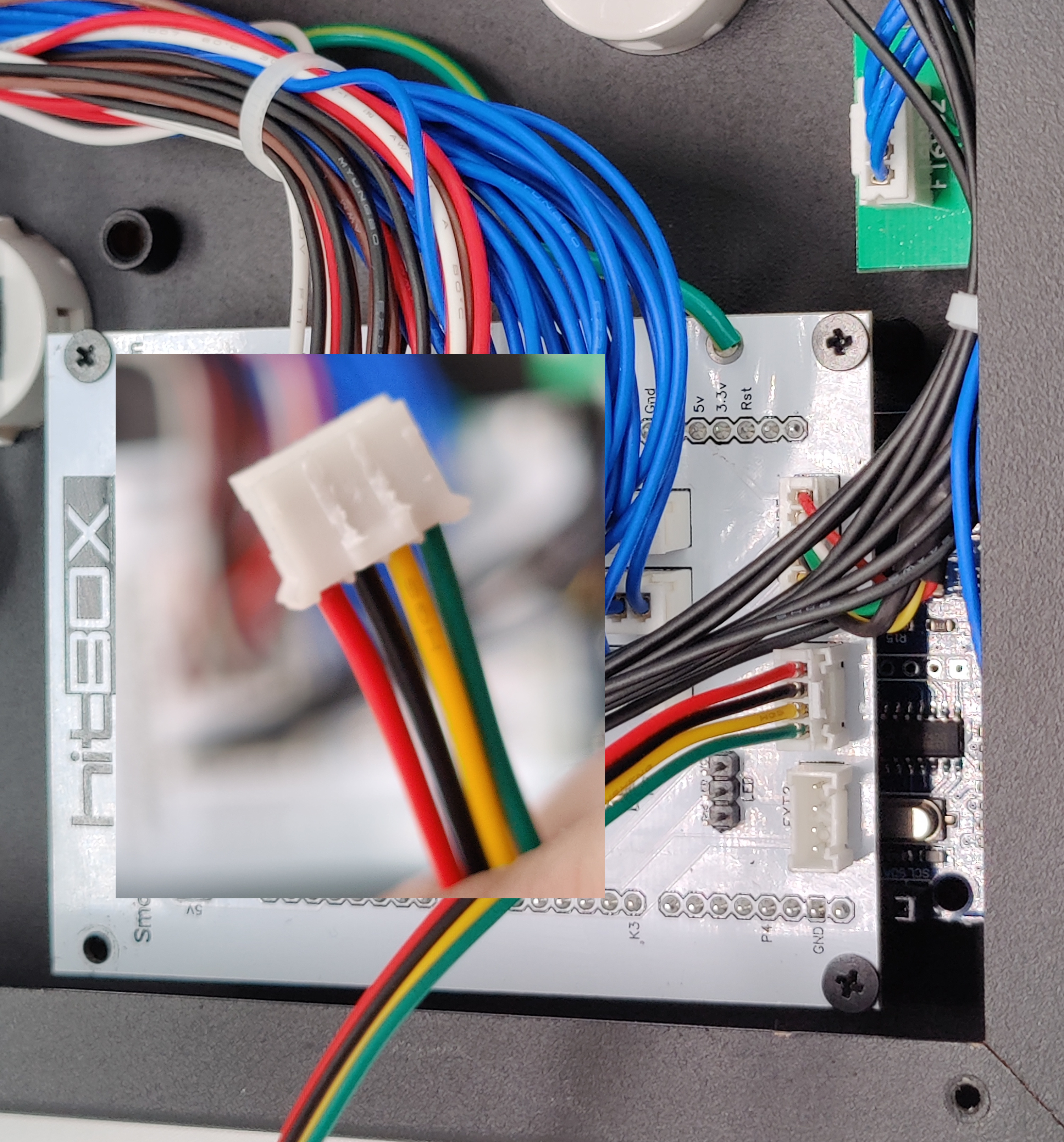
-
-
Now take the other 5 pin connector that we plugged into the hub earlier and plug it into the 5 pin on the LED Spy board labelled
JUSB1. If you do not plan to install leds you can proceed to Reassembly (Part 2) section. -
Assuming you are installing LEDs, take the 4 pin connector on the power harness connected to the battery and plug it into the port labelled
JPWR1 -
Now take the first LED cable in the chain and plug it into the
JLED1port on the led spy board.
Reassembly (Part 2)
-
Now that everything should be installed, we can replace the bottom panel and the 6 screws.
-
Now you may proceed to the LED Spy Designer documentation and follow the instructions there to set up your lighting, or use input display
Hit Box
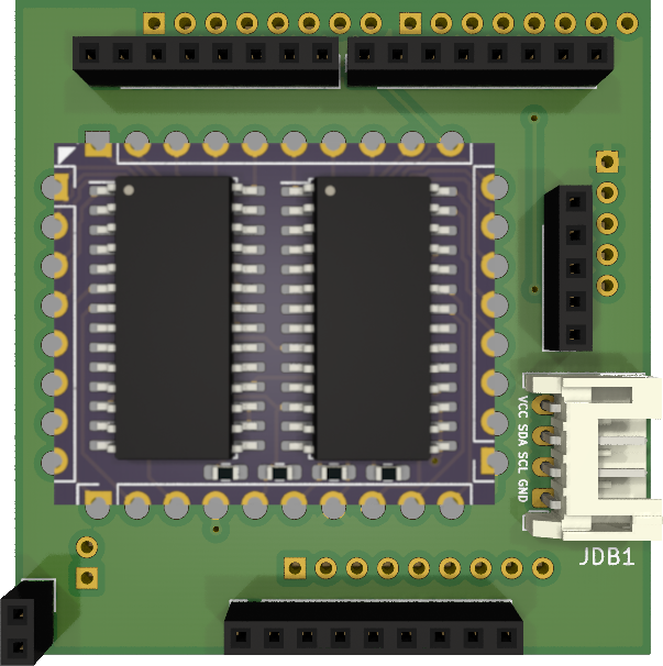
Daughterboard Info
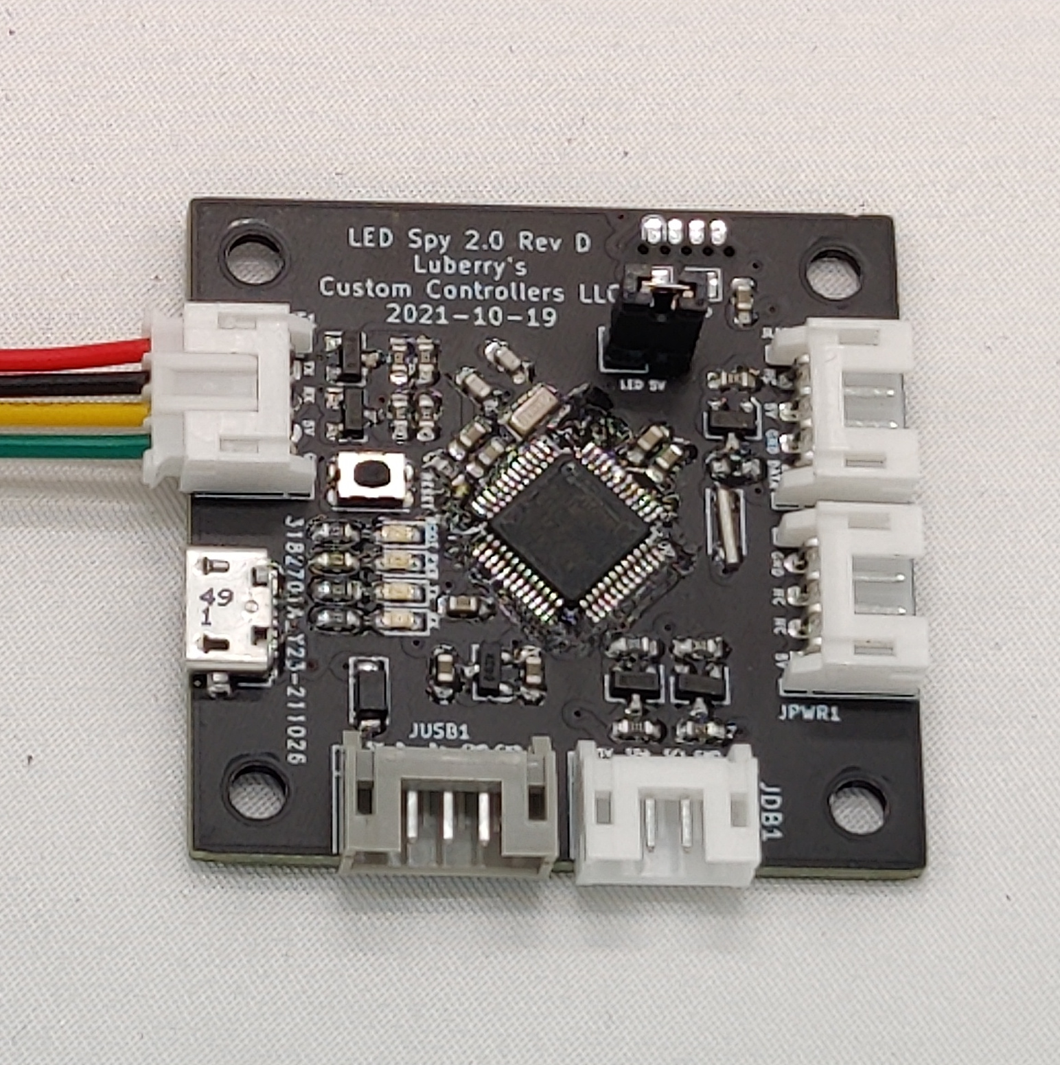
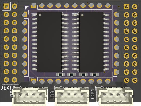
Below is a picture of the Hit Box Daughterboard for LED Spy which is a board meant to be placed between the breakout, and the green brook pcb in the controller.
Tools
- PH1 Screwdriver
Post June 2020 - 2.5MM Hex
Pre June 2020 - Cordless Drill
- Various Drill Bits
- Center Punch, this one is what i use.
- Safety Glasses (for use when drilling)
- Needle Nose Pliers (can make wire removal easier)
- Button Popout tool (optional, but it makes it way easier to remove buttons). I recommend this one from Paradise Arcade Shop 3
Materials
- 1x LCC LED Spy 2.0 Board
- 1x LCC Hit Box Daughterboard for LED Spy
- 1x USB Passthrough
- we sell a usb wiring kit that is plug and play with LED Spy here that is based off of the Neutrik mounting pattern
- 16x LCC 5050 LED Modules or other neopixel/ws2812 led options that supply 2x LEDs per actuator. (optional) 3
- 15x Paradise Kaimana J2 3" Harness (optional) 3
- 1x Paradise Kaimana J2 6" Harness (optional) 3
- 15x 24mm Transparent/Clear buttons 3
- 1x 30mm Transparent/Clear buttons 3
- Way to fasten LEDS 3
- Sanwa Buttons - the best way to fasten sanwa buttons is the LCC Sanwa LED Module Mounting Clip
- Seimitsu Buttons - the LCC modules fit snugly around the seimitsu switch so no mounting mechanism is required.
- Crowns/Gamerfingers/Other - a couple small dabs of hot glue are your friend in this instance as i have yet to make a reliable clip design for my modules
- Masking/painters tape used to protect the paint on the surface during cutting 3
- Some way to mark wires (optional, but recommended)
- pen and masking/painters tape work wonders
- Magnet or cup to keep screws together (optional, but recommended)
- 3mm Adhesive Standoffs.
Disassembly
Step 7 you can follow the official guide for disassembly, as it goes much more in depth than this guide.
-
Place your controller onto its face, try and use a soft surface to avoid scratching it.
-
Remove the 6x Phillips Screws (
Post June 2020), the 4 phillips and 2 hex screws (later Pre June 2020 models), or the 4 rubber feet and 2 hex screws (older models) and remove the base plate.if you have a gen 3 base plate is a good surface to place the controller on top of since it is padded with foam. -
Now, if your controller has a
-
Now is when you should label the wires, this is optional, but will help you later on. You may also take a picture of the wiring. The easiest way to label the wires is use a piece of masking tape around each pair of wires. and write unique labels on each.
-
Now it is time to remove the wires. There are 2 variants of connector used on the Hit Box,
Pre June 2020used vertical style connector, whereasPost June 2020currently uses right angle connectors. The right angle connectors are significantly easier to remove than the vertical style.-
Horizontal Removal:
There are 2 main methods for removal of right angle/horizontal quick disconnects.
- Method 1: Use your fingers as demonstrated by the below gif, courtesy of Hit Box Arcade LLC.
- Method 2: Use your needle nose pliers while holding the controller down with your other hand as demonstrated by the below gif, courtesy of Hit Box Arcade LLC.
- Method 1: Use your fingers as demonstrated by the below gif, courtesy of Hit Box Arcade LLC.
-
Vertical Removal:
Since the vertical quick disconects are on super tight, you will want to hold the controller down with one hand, grab the disconnect with the needle nose in the position noted below, and pull straight up.
Image courtesy of Hit Box Arcade LLC
-
-
Remove the buttons from the controller, either using the button pop out tool mentioned earlier, or by squeezing the tabs on the buttons with your fingers.
-
Next you need to remove the plastic rivets from the controller, this can be done by pressing on the center pin from the back side with a screwdriver. They should pop out pretty easily this way. Place the rivets somewhere safe as you will need them to reinstall the plexi later.
Image courtesy of Hit Box Arcade LLC
-
Remove the plexi and set it aside somewhere it won't be scratched (especially if you plan to reuse it)
- Now you must remove the usb plug from the main board. It should be a white 5 pin connector as pictured below.
- Now remove the 5 phillips screws as indicated below, and remove the main pcb. We can now set this aside for later.

Side USB Install
Now that we are down to a mostly bare metal case, we can now mount our side usb port for the LED Spy board.
- Wrap the edges of your case in masking/painters tape to protect the case from being scratched. You may also want to tape the cable for the usb port out of the way as well.
- Pick a spot for your usb port. I like to position the port roughly in the spot pictured below.
- Print out the template, and trim it to be a small rectangle, and tape it to the side of the box where you wish to put the port.
- Now you can use your center punch to mark the centers of the 3 holes you wish to drill.
- Drill pilot holes in all 3 spots with a 3mm or 1/8" drill bit (this is the final size for the two mounting holes)
- Now take a 24mm hole saw or step bit and drill out a 24mm hole in the side of the case.
- Remove the tape from the controller now and clean up all the filings.
- Use a deburring tool or some sandpaper to clean up the hole.
- Now you can screw in your usb port.
LED Spy Board Daughterboard Installation
-
Take the mainboard you removed earlier and use an exacto knife or a small flathead to remove the adhesive from the connectors that helps secure the main pcb. It should come off with some light scraping.
-
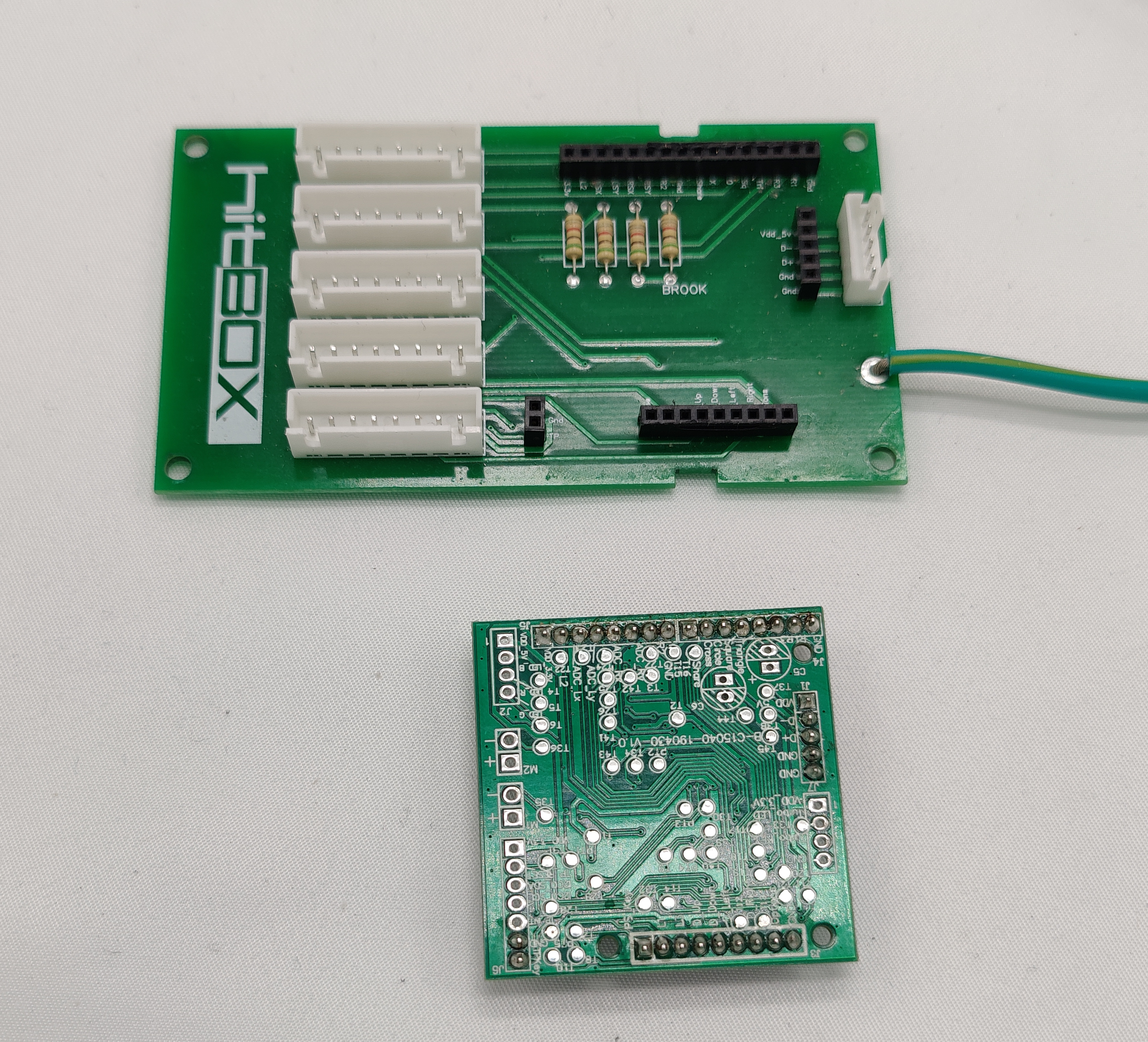
Gently pull the two boards apart. You may need to slowly rock it side to side. You should now be left with two separate pcbs.
-
Now, install the
Hit Box Daughterboard for LED Spyinto the larger breakout board as pictured below.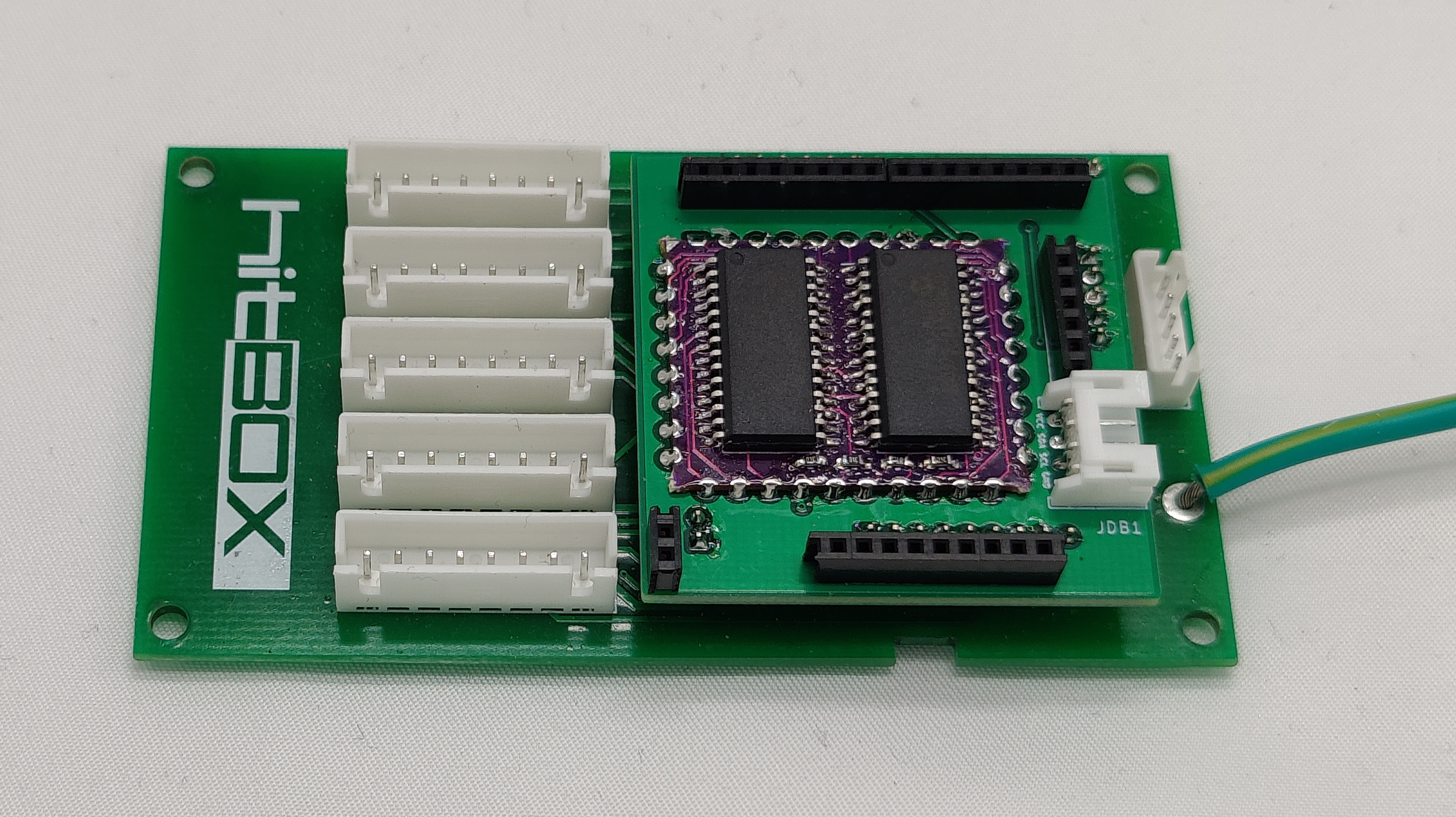
-
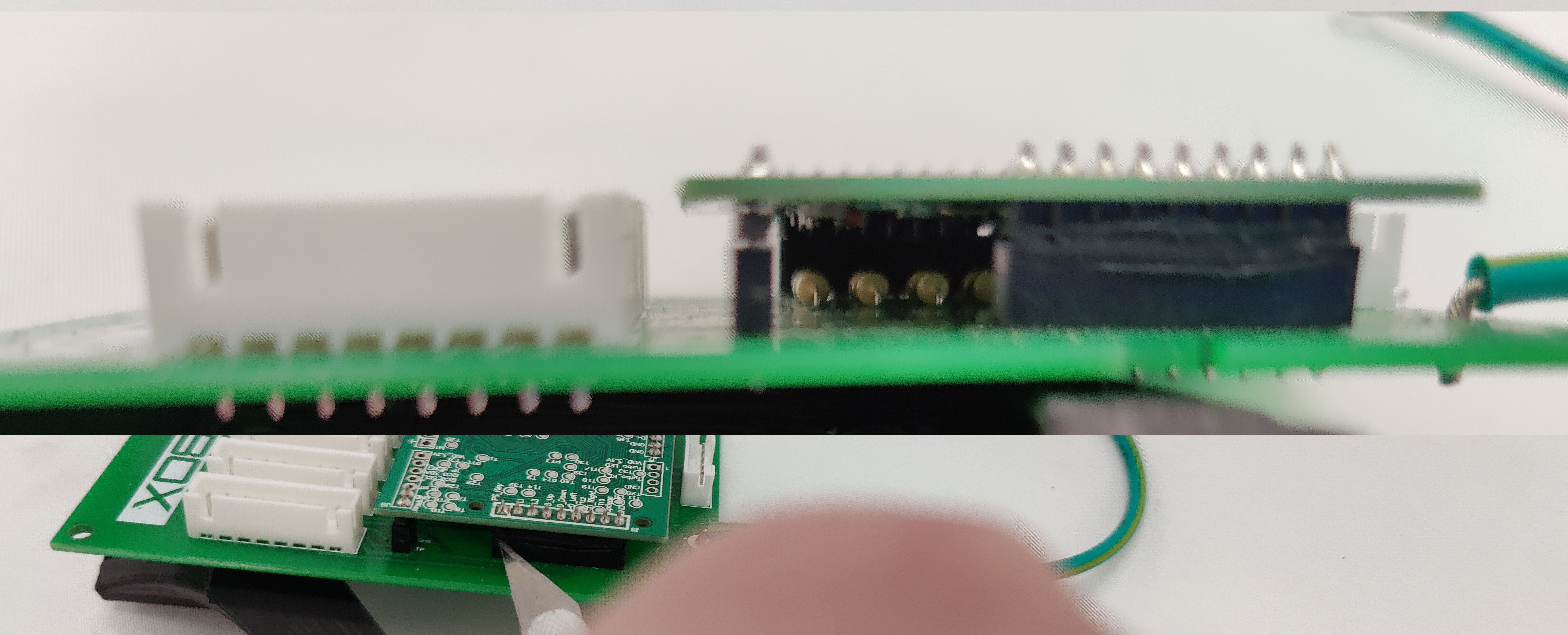
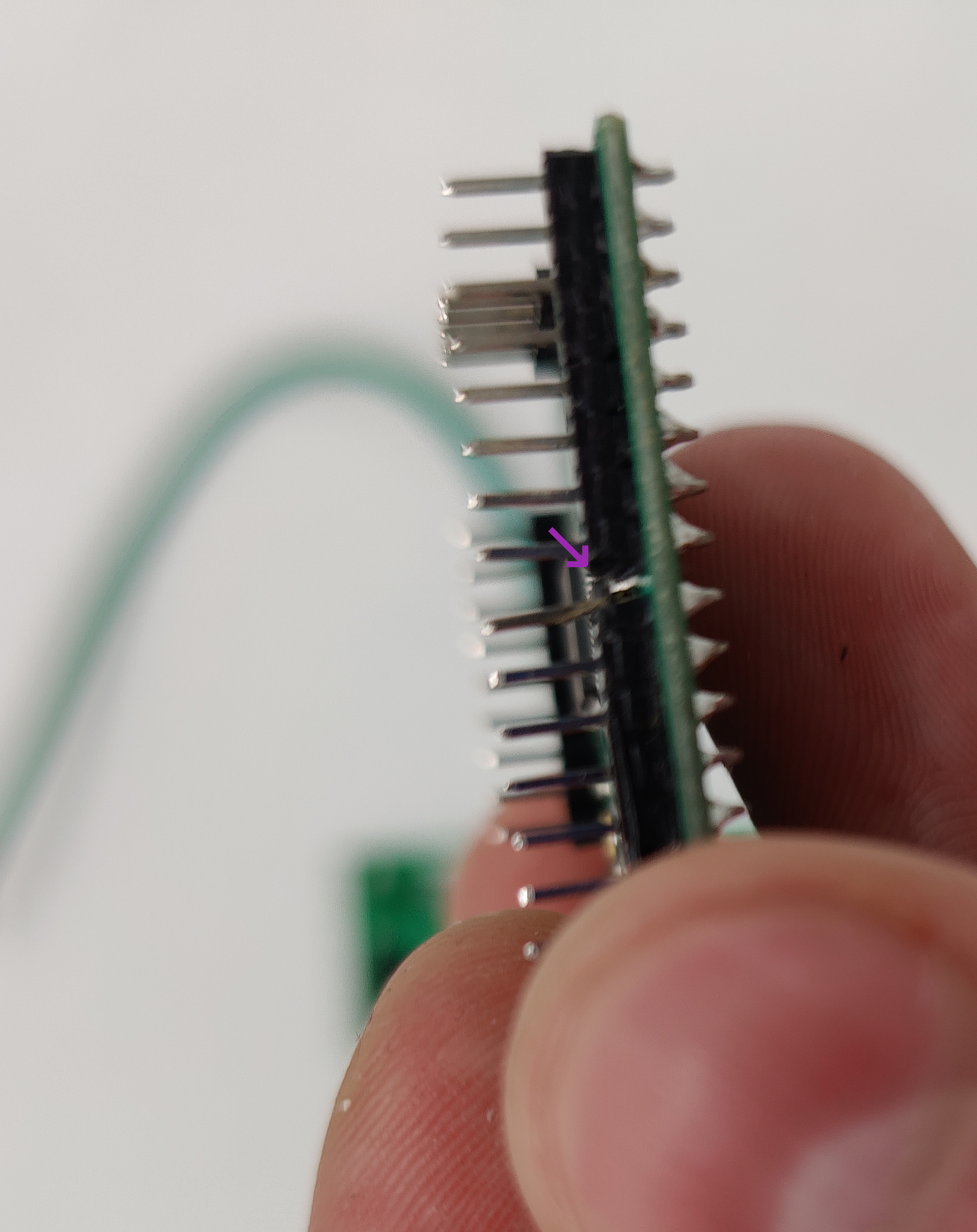
Now, because of how the brook on the Hit Box was assembled, we it is a good idea to remove some of the plastic in the center of the pictured connectors to relieve stress on the joint, as shown below.
-
Now insert the brook into the socket on the daughterboard as shown below.
-
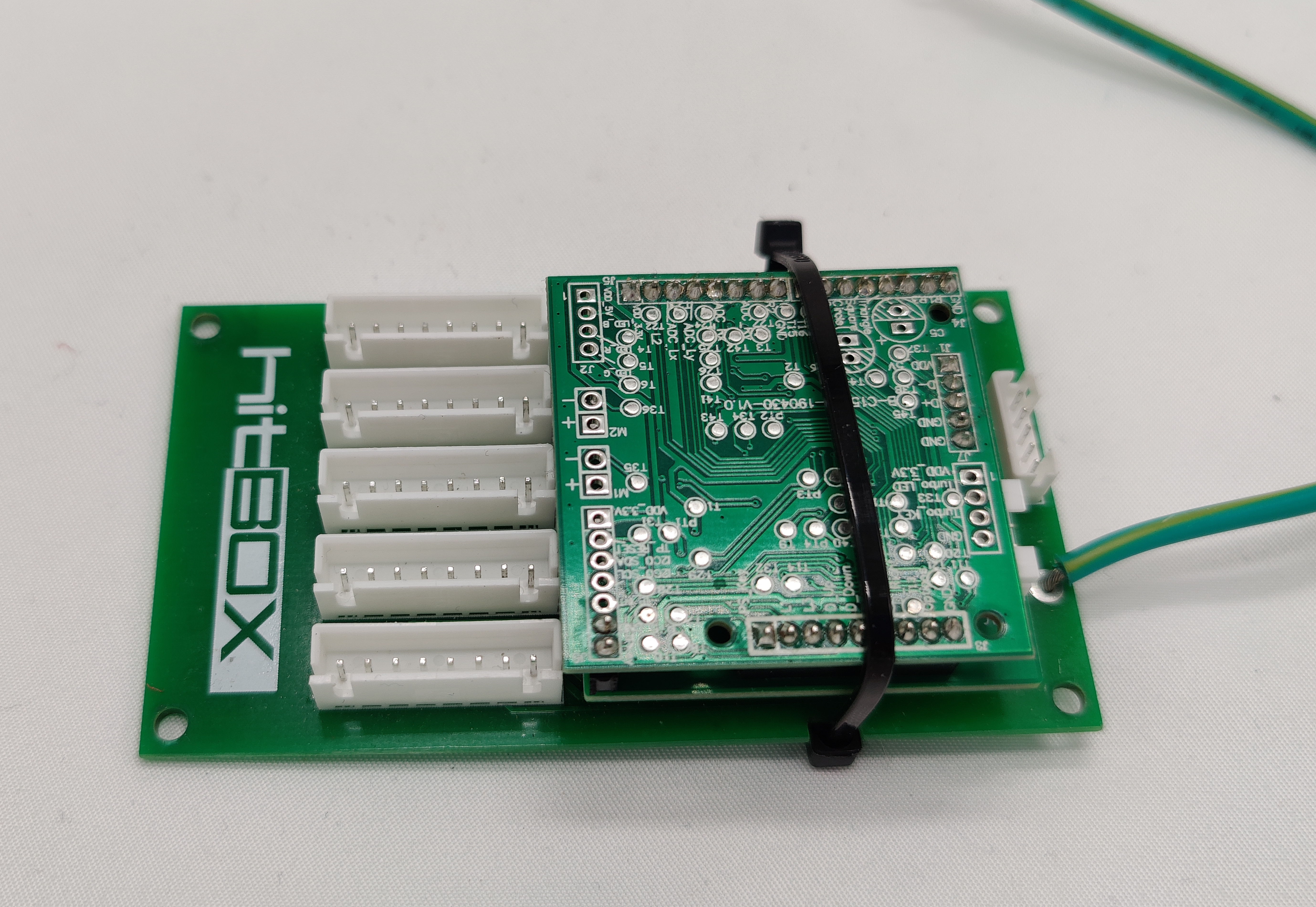
Now take the included 8" zip tie and use it to secure the stack together. This will help prevent vibrations from shaking any of the boards loose.
-
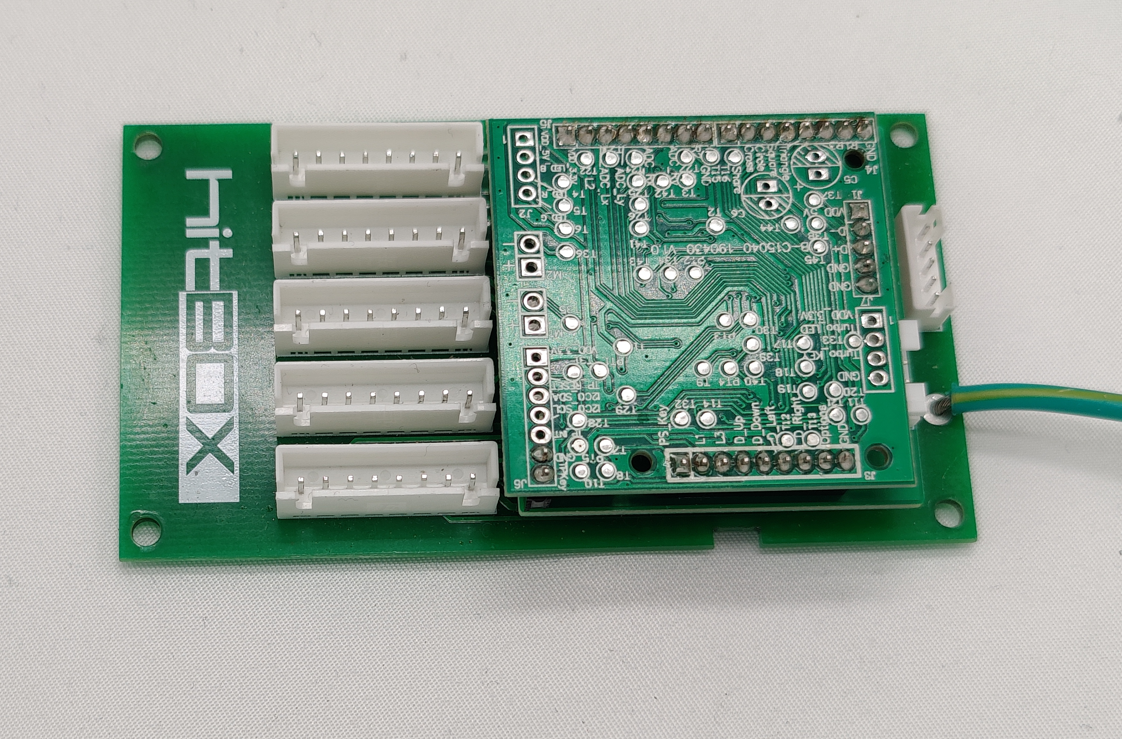
Reinstall your main pcb stack now following the reverse of steps
9 and 10of Disassembly. It should look like the image below.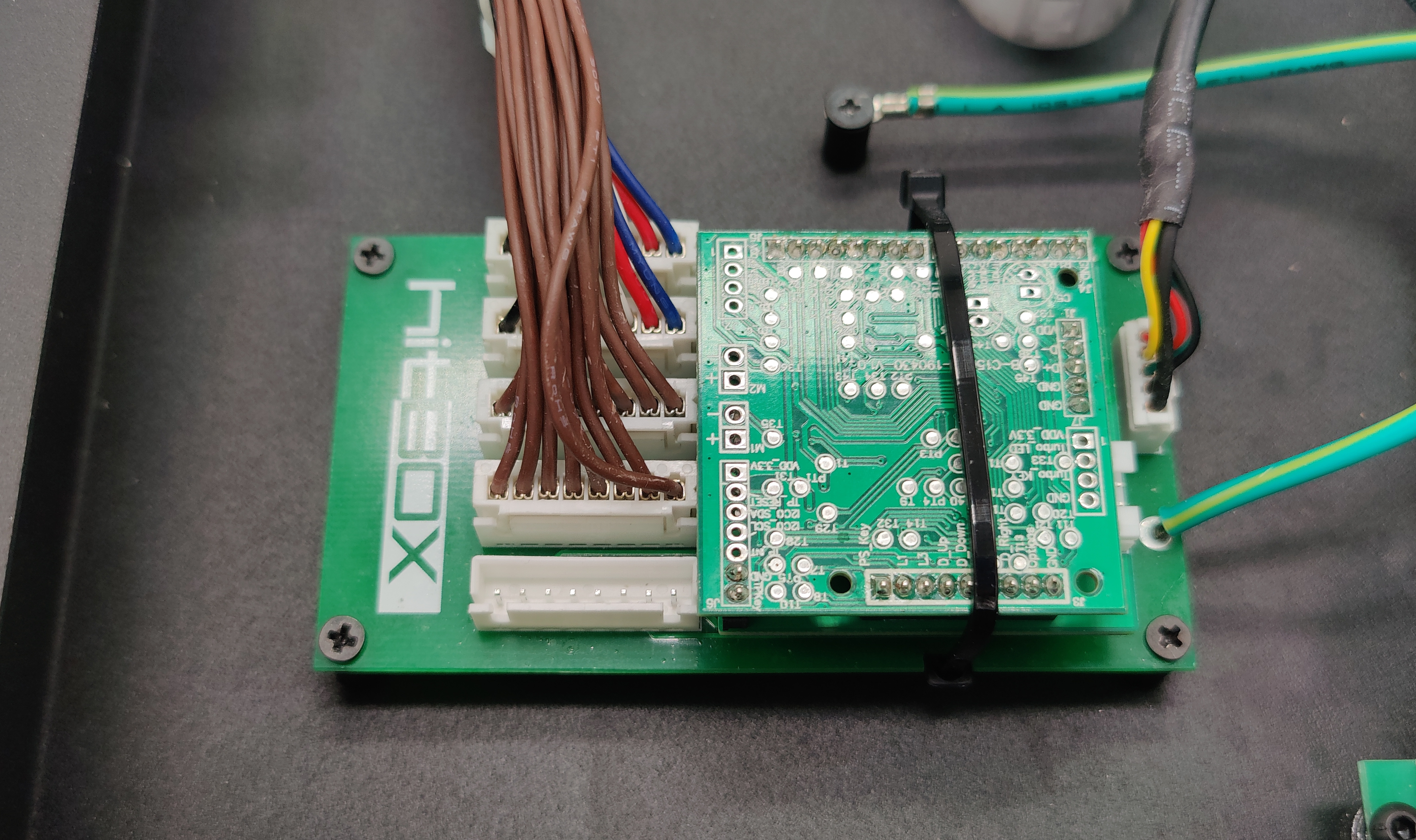
-
You may now reinstall your buttons as well, but do not plug in the cables yet.
LED Spy Board Installation
Now the LED Spy Board can be installed.
-
First find a suitable spot to mount your board in your case there alot of open space towards the center of the case next to the main pcb.
-
Plug the included 4 pin JST cable into the port labelled JDB1 on the LED Spy PCB as pictured below.
-
Next you must mount the PCB, the easiest way is to use the 3mm standoffs mentioned in materials.
-
Now plug the other end of the 4 pin JST cable into the daughterboard you installed earlier.
-
Now connect the LED Spy Board to a usb passthrough either through the 5 pin
JUSB1or the micro USB Port labeledJUSB2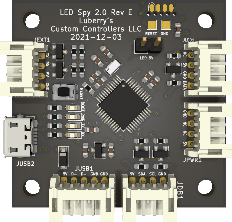
-
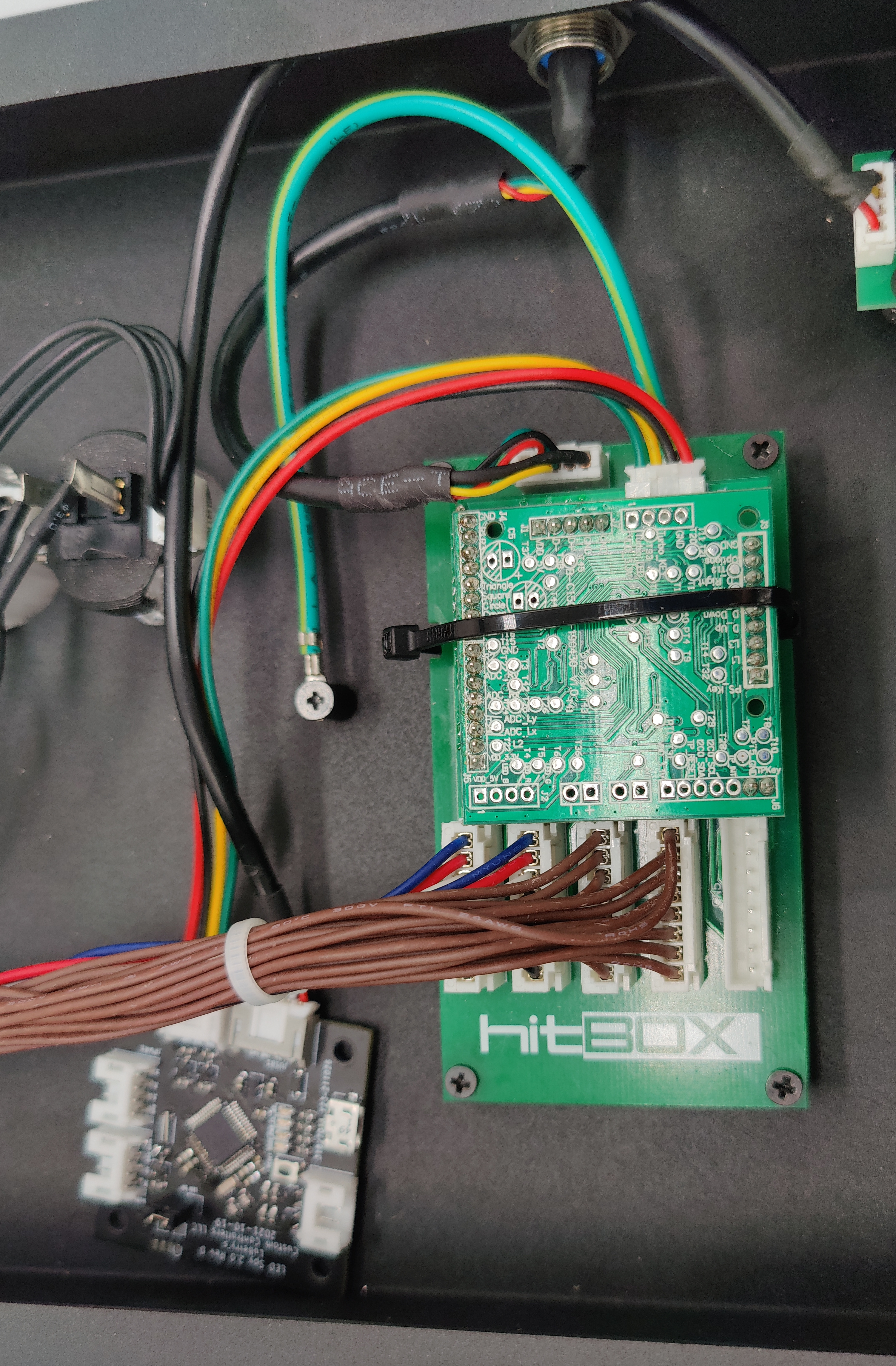
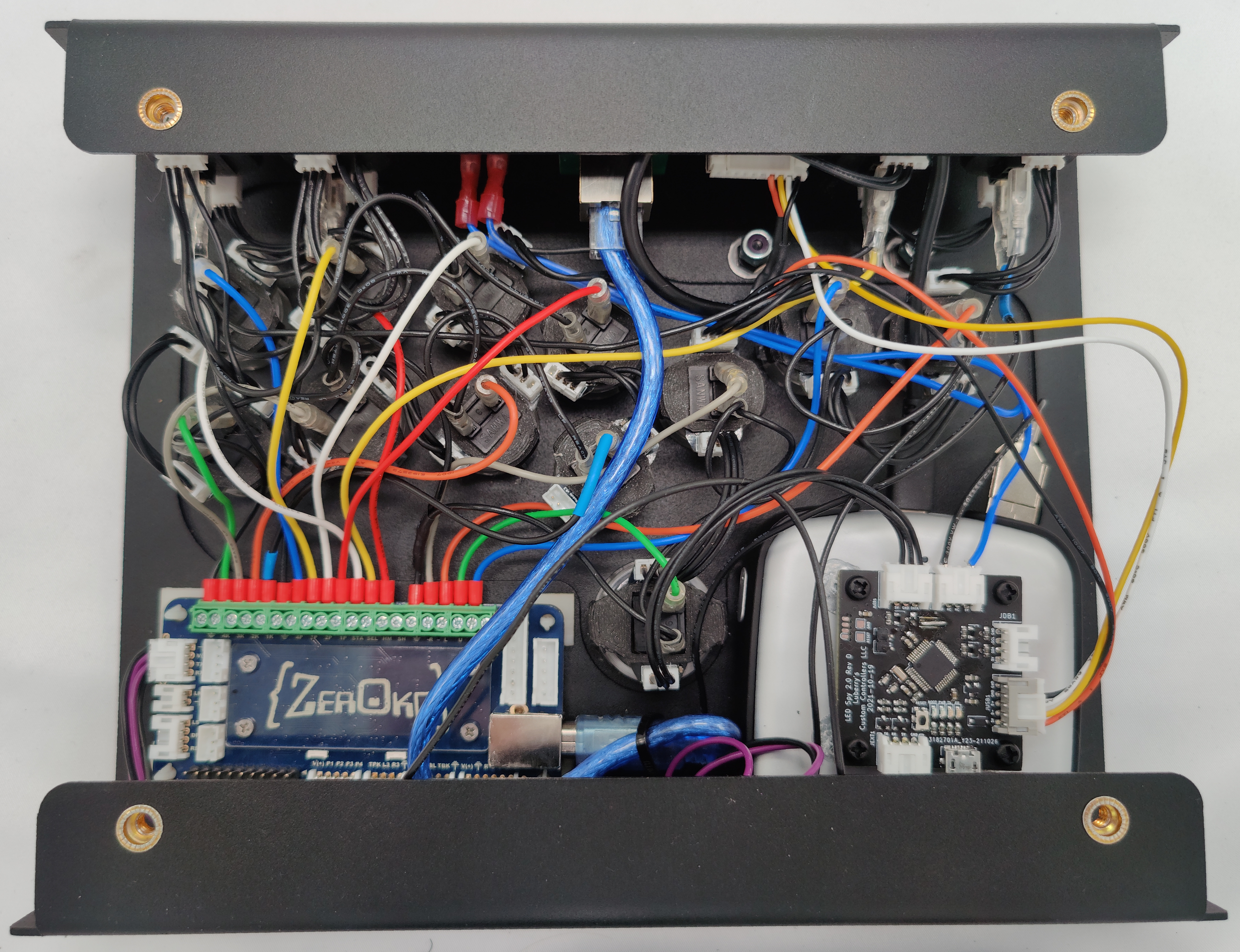
You should now have something similar to below (except the LED Spy board would be secured)
LED Installation
The next step is to install the LED Modules, this guide will assume you are using the LCC 5050 LED Modules.
- Position all of your modules so that they don't interfere with eachother. you may have to rotate the buttons some to get them all to fit. (its a bit of a puzzle).
- Now either secure the modules with some hot glue, or my LED clips (for sanwas) making sure the wires quick disconnects will still plug in.
- Next we need to connect the leds. There are two different connectors on the leds. The 3 pin is the input, and the 4 pin is the output. Route your cables as you see fit as you can always remap the positon in software, however you want the input to be pretty close to the main pcb. Below is probably the optimal layout, or close to it.
- Now, make sure you install the included jumper on the
LED 5Vpins to allow passthrough usb power for the leds. - Now plug the first led in the chain into the
JLED1port of the LED Spy board.
Reassembly
- Reattach all of your quick disconnect cables to their respective buttons.
- Reinstall the bottom plate.
- Now once you reassemble your controller you may proceed to the LED Spy Designer documentation and follow the instructions there to set up your lighting, or use input display
Brook/Generic
Tools
- Various screwdrivers
- Needle Nose Pliers (can make wire removal easier)
- Button Popout tool (optional, but it makes it way easier to remove buttons). I recommend this one from Paradise Arcade Shop.
Materials
- 1x LCC LED Spy 2.0 Board
- 1x LCC LED Spy 20 Pin Breakout
- LCC 5050 LED Modules or other neopixel/ws2812 led options that supply 2x LEDs per actuator. (optional) 3
- LED Cables, number will vary based on the number of buttons in your controller. Some options below.
- Paradise Kaimana J2 3" Harness (optional) 3
- Paradise Kaimana J2 6" Harness (optional) 3
- Paradise Kaimana J2 8.5" Harness (optional) 9" also works 3
- 1x usb Passthrough, can be neutrik, type c or whatever
- You can wire the charge circut to the same usb port as the data port, but if you wish to have a separate port you can use another if you wish
- 24mm or 30mm Transparent/Clear buttons depending on your case and layout 3
- Way to fasten LEDS 3
- Sanwa Buttons - the best way to fasten sanwa buttons is the LCC Sanwa LED Module Mounting Clip
- Seimitsu Buttons - the LCC modules fit snugly around the seimitsu switch so no mounting mechanism is required.
- Crowns/Gamerfingers/Other - a couple small dabs of hot glue are your friend in this instance as i have yet to make a reliable clip design for my modules
Daughterboard Pinout
|
|
|
LED Spy Board Installation
Now the LED Spy Board can be installed.
-
First find a suitable spot to mount your board in your case, make sure the included 4 pin JST PH cable can reach the
LED Spyboard and your brook board, or you may need to get a longer one/extend the existing one. -
Plug the included 4 pin JST cable into the port labelled JDB1 on the LED Spy PCB as pictured below.
-
Next you must mount the PCB. You can use some 3mm adhesive standoffs which you can pick up from our friends over at Bit Bang Gaming here.
-
Next plug the daughterboard into the Brook PCB or other generic PCB as shown, if you have more buttons than a standard brook pcb you can use the
EX0-EX10pins of the board as shown in the pinout.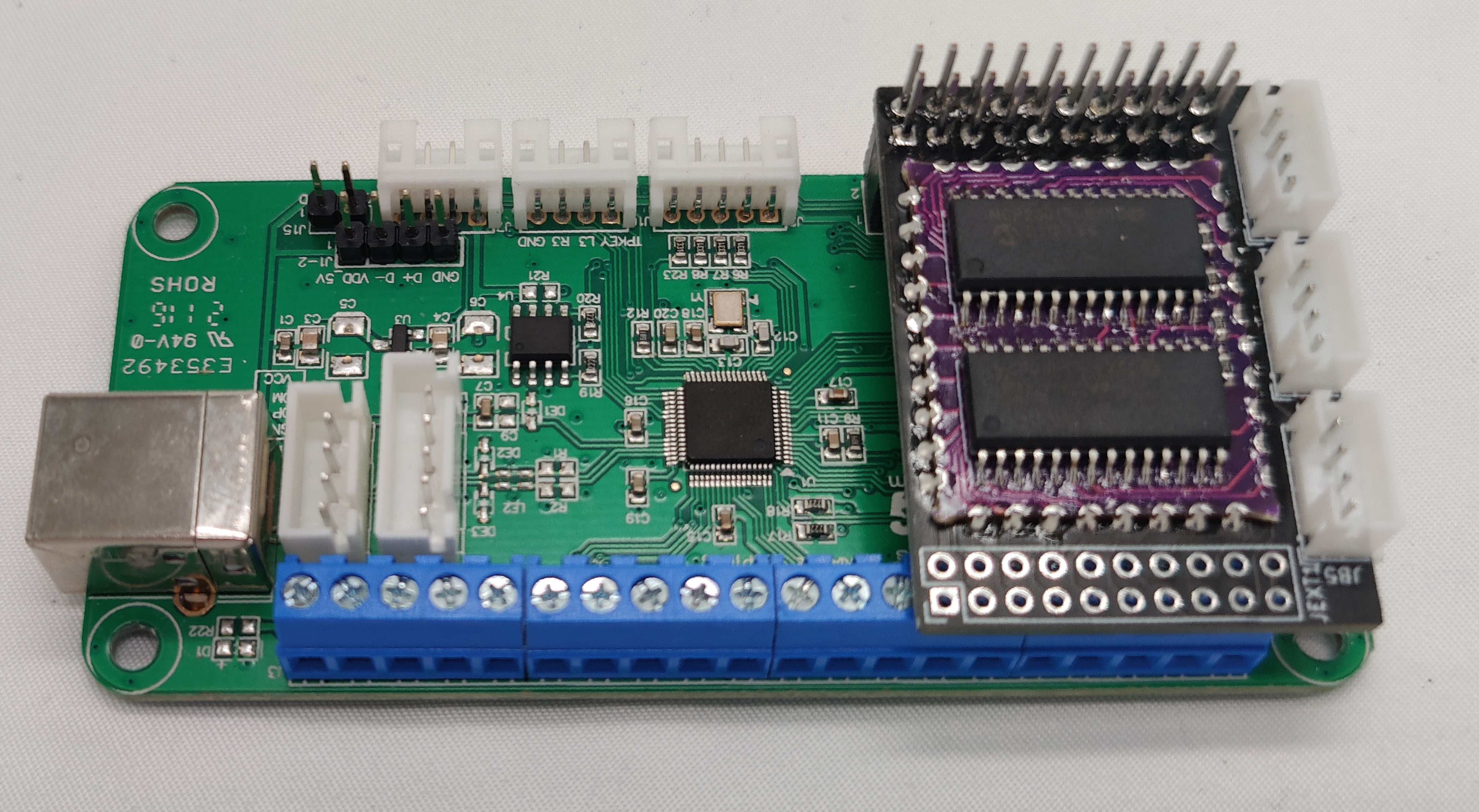
-
Now plug the LED Spy board into the Brook board, and use the 4 pin JST that came with the daughterboard to connect JB5 with the Touchpad/L3/R3 header on the board as shown below.
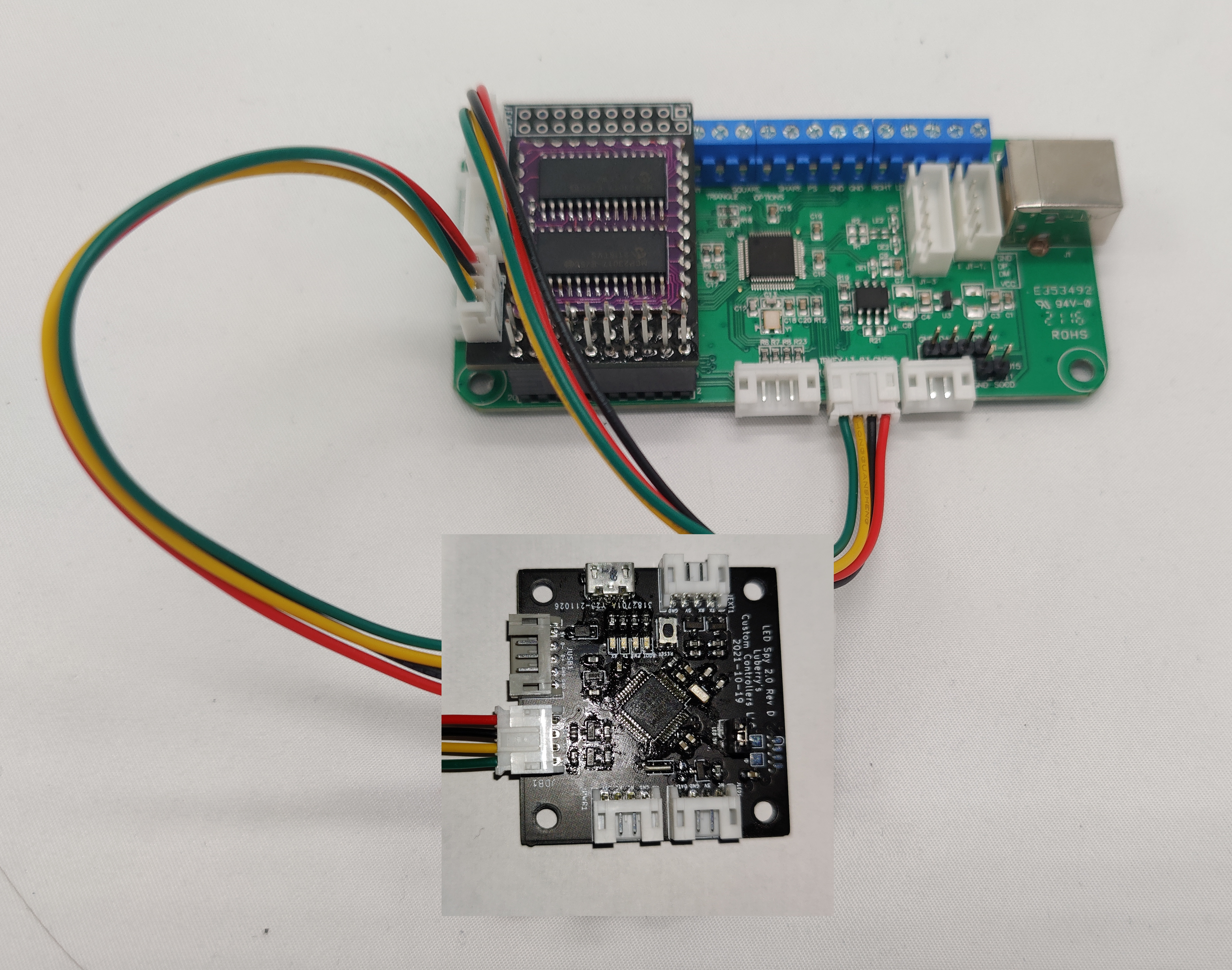
-
Now you can plug in a standard Brook 20 Pin Harness into
JB9and the 4 pin Touchpad/L3/R3 harness intoJB4as shown below.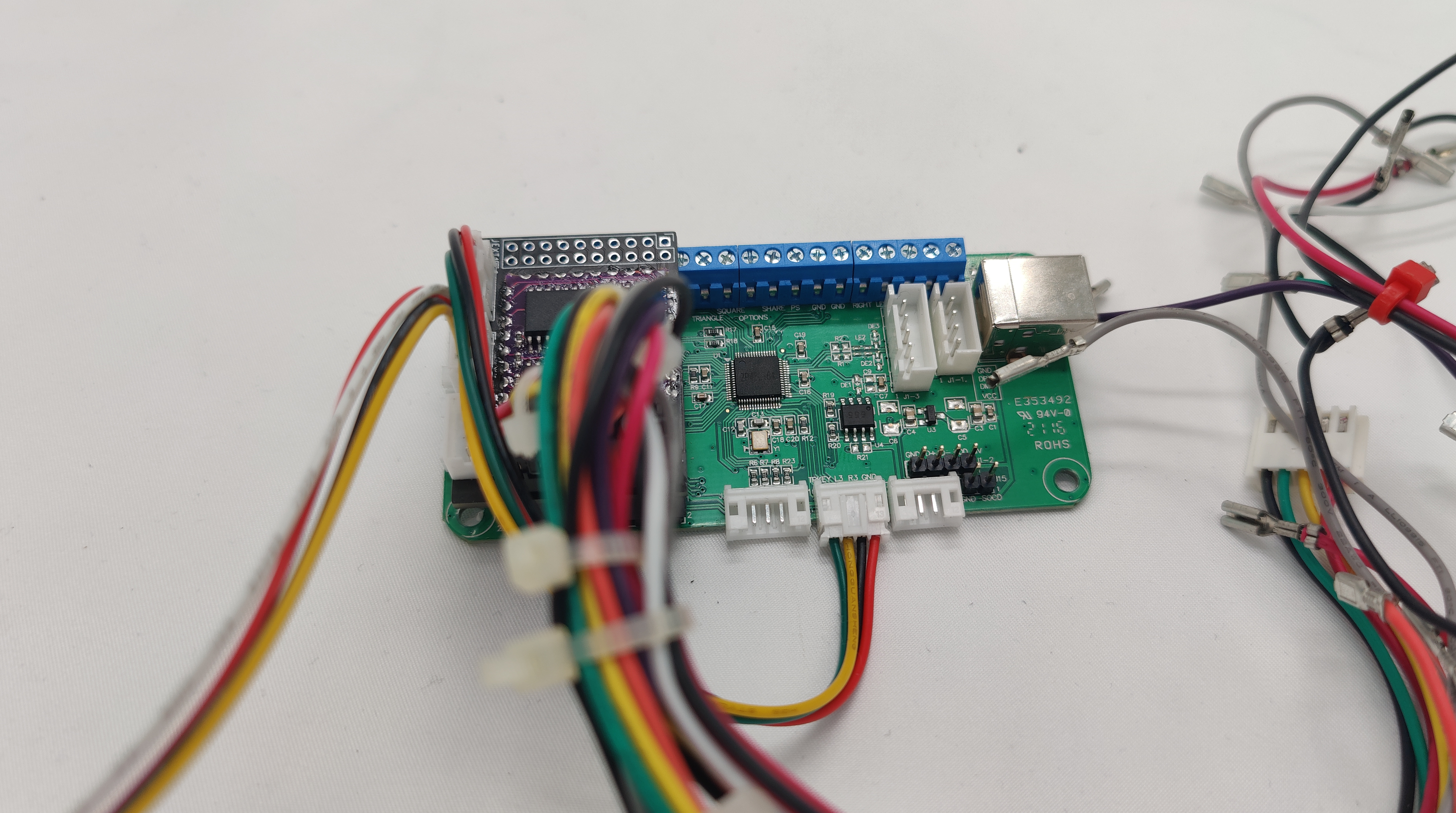
-
Now connect the LED Spy Board to a usb passthrough either through the 5 pin
JUSB1or the micro USB Port labeledJUSB2
LED Installation
The next step is to install the LED Modules, this guide will assume you are using the LCC 5050 LED Modules.
- Position all of your modules so that they don't interfere with eachother. you may have to rotate the buttons some to get them all to fit. (its a bit of a puzzle).
- Now either secure the modules with some hot glue, or my LED clips (for sanwas) making sure the wires quick disconnects will still plug in.
- Next we need to connect the leds. There are two different connectors on the leds. The 3 pin is the input, and the 4 pin is the output. Route your cables as you see fit as you can always remap the positon in software, however you want the input to be pretty close to the main pcb. You can see an example of how I wired my build below.
- Once the leds are wired, reconnect all of the quick disconnects to the correct buttons.
- Now plug the first led in the chain into the
JLED1port of the LED Spy board. - Now, make sure you install the included jumper on the
LED 5Vpins to allow passthrough usb power for the leds. - Now once you reassemble your controller you may proceed to the LED Spy Designer documentation and follow the instructions there to set up your lighting, or use input display
Bit Bang Gaming
Since these boards are meant to go in custom builds, these instructions will be much more generic than the guides for full controller addons.
Tools
- Various screwdrivers
- Cordless Drill 5 6
- Various Drill Bits 5 6
- Center Punch, this one is what i use. 5 6
- Safety Glasses (for use when drilling)
- Needle Nose Pliers (can make wire removal easier)
- Button Popout tool (optional, but it makes it way easier to remove buttons). I recommend this one from Paradise Arcade Shop.
Materials
- 1x LCC LED Spy 2.0 Board
- LCC 5050 LED Modules or other neopixel/ws2812 led options that supply 2x LEDs per actuator. (optional) 3
- LED Cables, number will vary based on the number of buttons in your controller. Some options below.
- Paradise Kaimana J2 3" Harness (optional) 3
- Paradise Kaimana J2 6" Harness (optional) 3
- Paradise Kaimana J2 8.5" Harness (optional) 9" also works 3
- 1x or 2x Usb Passthrough, can be neutrik, type c or whatever
- You can wire the charge circut to the same usb port as the data port, but if you wish to have a separate port you can use another if you wish
- 1x LCC LED SPY Battery Bank Wiring Kit (With Neutrik Switch Addon) (optional) 3
- 1x always on 4 battery bank, my recommendations are below.
- Voltaic Systems V50 (12800mAh)
- Voltaic Systems V25 (6400mAh)
- 1x USB power cable to run your battery bank and connect to your charge port of choice.
- 24mm or 30mm Transparent/Clear buttons depending on your case and layout 3
- Way to fasten LEDS 3
- Sanwa Buttons - the best way to fasten sanwa buttons is the LCC Sanwa LED Module Mounting Clip
- Seimitsu Buttons - the LCC modules fit snugly around the seimitsu switch so no mounting mechanism is required.
- Crowns/Gamerfingers/Other - a couple small dabs of hot glue are your friend in this instance as i have yet to make a reliable clip design for my modules
- Masking/painters tape used to protect the paint on the surface during cutting 5 6
- 3M VHB (Very High Bond) Tape (for mounting the battery bank) 3
Battery Bank Installation
- First you will need to use some VHB tape to secure the battery similar to the figure below. you can use more than pictured to secure it better.
Make sure to clean both the battery and inside of the case with some sort of degreaser, or isopropyl alcohol to promote better adhesion
- Peel the backing from the tape on the battery mount the battery in a position where you will still have access to the charge port and one output port for wiring.
- Next wire the battery harness to the power switch. If you purchased the wiring kit you should have received a cable similar to the one below (cable lengths may be different), and also if you elected for the neutrik switch port you should have a switch mount also pictured below.
- Now we plug the USB-A end of the harness into any of the available usb a ports, an example is pictured below.
- Assuming you have the voltaic battery. Plug in the charge cable type c port into the battery bank, and the other end into your usb passthrough.
LED Spy Board Installation
Now the LED Spy Board can be installed.
-
First find a suitable spot to mount your board in your case, make sure the included 4 pin JST PH cable can reach the
LED Spyboard and yourBit Bang Gamingboard, or you may need to get a longer one/extend the existing one. I happened to mount it to my battery bank and extend the cable due to case constraints. -
Plug the included 4 pin JST cable into the port labelled JEXT1 on the LED Spy PCB as pictured below.
-
Next you must mount the PCB. I have mounted it to the battery bank with some standoffs, superglue and screws because it is what i had on hand when writing this guide, however you can also use 3mm adhesive standoffs which you can pick up from our friends over at Bit Bang Gaming here.
-
Now plug the LED Spy board into the Bit Bang PCB as shown below.
-
Now connect the LED Spy Board to a usb passthrough either through the 5 pin
JUSB1or the micro USB Port labeledJUSB2
LED Installation
The next step is to install the LED Modules, this guide will assume you are using the LCC 5050 LED Modules.
-
First take the 4 pin connector on the power harness connected to the battery and plug it into the port labelled
JPWR1 -
Position all of your modules so that they don't interfere with eachother. you may have to rotate the buttons some to get them all to fit. (its a bit of a puzzle).
-
Now either secure the modules with some hot glue, or my LED clips (for sanwas) making sure the wires quick disconnects will still plug in.
-
Next we need to connect the leds. There are two different connectors on the leds. The 3 pin is the input, and the 4 pin is the output. Route your cables as you see fit as you can always remap the positon in software, however you want the input to be pretty close to the main pcb. You can see an example of how I wired my build below.
-
Once the leds are wired, reconnect all of the quick disconnects to the correct buttons.
-
Now plug the first led in the chain into the
JLED1port of the LED Spy board. -
Now once you reassemble your controller you may proceed to the LED Spy Designer documentation and follow the instructions there to set up your lighting, or use input display
-
Only if you wish to install LEDS, required for power switch installation ↩︎ ↩︎ ↩︎ ↩︎ ↩︎
-
These are good if you wish to install a rectangular power switch (to match the others on the controller), but are not required as everything can be accomplished with a file and patience ↩︎
-
Only needed if you wish to install leds ↩︎ ↩︎ ↩︎ ↩︎ ↩︎ ↩︎ ↩︎ ↩︎ ↩︎ ↩︎ ↩︎ ↩︎ ↩︎ ↩︎ ↩︎ ↩︎ ↩︎ ↩︎ ↩︎ ↩︎ ↩︎ ↩︎ ↩︎ ↩︎ ↩︎ ↩︎ ↩︎ ↩︎ ↩︎ ↩︎ ↩︎ ↩︎
-
Always on battery banks are recommended, as there is not enough startup current, and some of the smarter battery banks won't turn on, or will shut off after some time ↩︎ ↩︎
-
If your case does not have provisions for an extra usb port ↩︎ ↩︎ ↩︎ ↩︎
-
If your case does not have provisions for a power switch ↩︎ ↩︎ ↩︎ ↩︎