Before You Begin
Before beginning your installation of LED Spy, There are a few prerequisites.
Warning
You are installing LED Spy at your own risk, Luberrys Custom Controllers LLC is not responsible for any damage to your controller caused by modifying it.
Power
To protect the console, and your controller. Ensure you have enough power delivery for the leds you are installing. Most usb devices should be able to provide enough power to run a standard controller with 16-20 compatible LED modules. However if you notice jitter/flickering when plugged into the console, you are probably running low on power, and should use a battery bank instead.
Battery Bank Required
Some controller types require a battery bank due to power limitations of the console they support. Please ensure the JPWR1 jumper is removed to ensure the console does not try and power the lighting. If you only wish to take advantage of input display, a battery bank is not required.
My recommended battery bank is either the Voltaic Systems V50 or the V25 as they do not have automatic shut off, which will be triggered on most battery banks only running leds. They also feature pass through charging, so you can charge while using the leds.
-
Smash Box - requires a battery bank, as the GameCube and GameCube adapters cannot supply enough power to run leds
-
Zero KO - as this board targets classic controllers, the voltages needed to run the leds may not be provided by this board depending on console. Therefore a battery bank is required.
Pinouts and Information

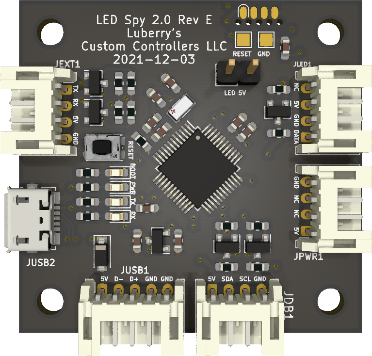
| Connector | Description |
|---|---|
| JUSB1 | usb port for input display and programming uses a JST-PH5 connector |
| JUSB2 | micro usb port, serves the same function as JUSB1 just an alternate connector |
| JEXT1 | expansion port for communicating with other controller hardware, such as the Bit Bang Gamming Zero KO and the Hit Box Arcade Smash Box |
| JDB1 | expansion port to connect to first party daughterboards such as the 20Pin Generic Daughterboard, and the Hit Box daughterboard |
| JPWR1 | power input for leds for use when being used with a low power board. LED 5V jumper should be removed when working in this mode |
| JLED1 | connection to WS2812 LED modules |
| LED 5V | jumper to allow usb to supply power to the leds. remove this if using an external power source |